Refrigeration cycle device

A refrigeration cycle and refrigerant technology, used in refrigerators, refrigeration components, refrigeration and liquefaction, etc., can solve the problems of difficulty in obtaining superheat, increase in heat exchange, and deterioration of refrigeration cycle refrigeration coefficient, and achieve improved efficiency and improved refrigeration. The effect of coefficients

Inactive Publication Date: 2017-05-10
DENSO CORP
View PDF9 Cites 10 Cited by
  • Summary
  • Abstract
  • Description
  • Claims
  • Application Information

AI Technical Summary

Problems solved by technology

[0014] In the case where the evaporator achieves the same degree of superheat as in the prior art, in the evaporator of the above prior art, since the difference between the temperature of the blown air and the temperature of the refrigerant is large, it is possible to use a relatively small heat exchange area. A specified amount of superheat is obtained, but in the evaporator of this research example, since it is necessary to obtain superheat between the refrigerant and the cooling water whose temperature is very low relative to the supply air, it is difficult to obtain superheat and there is a refrigeration cycle Concerns about deterioration of controllability (variation suppression, stability) when the load fluctuates
[0015] In addition, when the degree of superheat is obtained in a state where the temperature difference between the refrigerant and the cooling water is small, it is necessary to increase the temperature difference between the refrigerant and the cooling water by lowering the temperature of the refrigerant in the evaporator so that the heat exchange amount increase, but in this case, there is a concern that the refrigerant density sucked into the compressor will decrease and the cooling coefficient (COP) of the refrigeration cycle will deteriorate.

Method used


Image

  • Refrigeration cycle device
  • Refrigeration cycle device
  • Refrigeration cycle device

Examples


no. 1 Embodiment approach

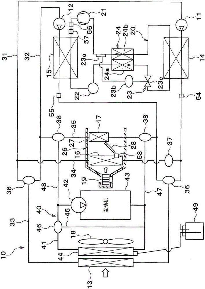
[0041] figure 1 The illustrated refrigeration cycle device 10 is used to air-condition the vehicle interior to an appropriate temperature. In the present embodiment, the refrigeration cycle device 10 is applied to a hybrid vehicle that obtains driving force for vehicle running from an engine (internal combustion engine) and a running electric motor.

[0042] The hybrid vehicle according to the present embodiment is configured as a plug-in hybrid vehicle capable of charging a battery (vehicle battery) mounted on the vehicle with electric power supplied from an external power supply (commercial power supply) when the vehicle is parked. As the battery, for example, a lithium ion battery can be used.

[0043] The driving force output from the engine is used not only for driving the vehicle but also for operating the generator. In addition, the electric power generated by the generator and the electric power supplied from the external power source can be stored in the battery, an...

no. 2 Embodiment approach

[0199] In the above-mentioned first embodiment, the high-pressure side refrigerant of the refrigerant circuit 20 heats the blown air blown toward the vehicle interior via the cooling water. Figure 9 As shown, the high-pressure side refrigerant of the refrigerant circuit 20 does not heat the blown air blown toward the vehicle interior through the cooling water.

[0200] The refrigerant circuit 20 has an indoor condenser 60 , an outdoor condenser 61 , an outdoor condenser bypass passage 62 , and a three-way valve 63 . The indoor condenser 60 and the outdoor condenser 61 are radiators that dissipate heat from the high-pressure side refrigerant in the refrigerant circuit 20 .

[0201] The interior condenser 60 is a refrigerant-air heat exchanger for exchanging heat between the high-pressure side refrigerant discharged from the compressor 21 and the blown air blown toward the vehicle interior. The indoor condenser 60 is a condenser for condensing the high-pressure side refrigeran...

no. 3 Embodiment approach

[0207] In the above-mentioned embodiment, the temperature type expansion valve 23 is used as the decompression device for decompressing and expanding the liquid-phase refrigerant flowing out of the cooling water heater 15, but in this embodiment, as Figure 10 As shown, the expansion valve 23 adopts an electric expansion valve 65 as a decompression device.

[0208] The electric expansion valve 65 changes the area (opening degree) of the throttle flow path 65b by an electric mechanism 65a. The throttle flow path 65 b is a decompression device for decompressing the high-pressure refrigerant that radiates heat in the cooling water heater 15 .

[0209] The operation of the electric mechanism 65 a is controlled by the control device 50 . The electric mechanism 65 a and the control device 50 are a superheat degree control unit that controls the degree of superheat of the low-pressure refrigerant that is heat-exchanged in the internal heat exchanger 24 .

[0210] The detection sign...


PUM


Abstract

This refrigeration cycle device comprises: a low temperature side pump (11) which takes in and discharges a low temperature side heat carrier; a compressor (21) which takes in, compresses, and discharges a refrigerant; a heat dissipating unit (15) which dissipates heat from high-pressure refrigerant discharged from the compressor (21); a pressure reducing device (23c) which reduces the pressure of the high-pressure refrigerant for which the heat has been dissipated by the heat dissipating unit (15); an internal heat exchanger (24) which exchanges heat between the high-pressure refrigerant flowing from the heat dissipating unit (15) and low-pressure refrigerant discharged from a heat carrier cooling unit (14); a low-pressure refrigerant temperature sensing unit (23a) which detects or senses the temperature associated with the temperature of the low-pressure refrigerant that exchanged heat in the internal heat exchanger (24); and an overheating control unit (23b) which controls the degree of overheating of the low-pressure refrigerant that exchanged heat in the internal heat exchanger (24) on the basis of the temperature detected or sensed by the low-pressure refrigerant temperature sensing unit (23a).

Description

[0001] Cross-references to related applications [0002] This application is based on the JP Patent application 2014-125306 for which it applied on June 18, 2014, The content of an indication is incorporated in this application as a reference. technical field [0003] The present invention relates to a refrigeration cycle device provided with an internal heat exchanger. Background technique [0004] Conventionally, Patent Document 1 describes a refrigeration cycle apparatus that uses carbon dioxide as a refrigerant and includes an internal heat exchanger. The internal heat exchanger is a heat exchanger that exchanges heat between the refrigerant from the radiator and the refrigerant from the evaporator. [0005] When carbon dioxide is used as the refrigerant, the pressure on the high pressure side becomes higher than the critical pressure in summer, and the power consumption of the compressor increases, thereby deteriorating the cooling coefficient (COP) of the refrigeratio...

Claims


Application Information

Patent Timeline
Patent Type & Authority Applications(China)
IPC IPC(8): F25B1/00B60H1/08B60H1/32F25B40/00F25B41/06
CPCF25B1/00F25B40/00B60H2001/00928B60H1/00899B60H1/32284B60H1/00342B60H1/004B60H1/00485
Inventor 榎本宪彦加藤吉毅杉村贤吾梯伸治
Owner DENSO CORP
Why Eureka
Try Eureka