A mechanical arm structure that can adjust the contact force and reduce the influence of deformation

A technology of mechanical arm and contact force, applied in the direction of manipulator, claw arm, manufacturing tools, etc., can solve the problems of position deviation, force deformation of the mechanical arm, etc., to reduce the amount of deformation, reduce the change of the axis angle, and the electrical connection simple effect

Active Publication Date: 2018-11-09
DALIAN UNIV OF TECH
View PDF5 Cites 0 Cited by
  • Summary
  • Abstract
  • Description
  • Claims
  • Application Information

AI Technical Summary

Problems solved by technology

If only microscopic vision is used, it is only suitable for the situation where there is no assembly force and processing force in the assembly or processing process, otherwise the mechanical arm connected to the end effector is deformed by force, resulting in position deviation

Method used


Image

  • A mechanical arm structure that can adjust the contact force and reduce the influence of deformation

Examples


Embodiment Construction

[0020] Specific embodiments of the present invention will be described in detail below in conjunction with technical solutions and accompanying drawings.

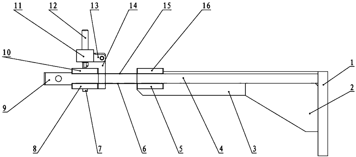
[0021] The robotic arm consists of a body, a tool unit and a plunger unit. The body includes the bottom plate of the robotic arm 1, the mounting plate of the robotic arm 4, the mounting plate of the visual device 3, the side plate and the rib 2; the tool unit includes the suction cup adapter 9, the end effector, the upper and lower springs 6, 15 and the lower pressure plate of the spring 1, 5, spring plate lower plate 2 8, spring plate upper plate 10, spring plate upper plate 2 16; the plunger unit includes a plunger 12, a plunger fixed angle seat 11, a micro switch 13, a micro switch connecting plate 14 and The supporting beams consist of 7.

[0022] Different end effectors can be selected for different operation objects, and the use of vacuum suction cups as end effectors is used as an example to illustrate.

[0023] Fi...


PUM


Abstract

The invention discloses a mechanical arm structure capable of adjusting contact force and reducing deformation influences, and belongs to the field of precision machines. A mechanical arm is composed of a body, a tool unit and a plunger unit. The body is used for connecting the tool unit and the plunger unit with a guide rail or a platform of an assembling system. The tool unit is used for fixing an end effector and ensuring that the axis of the end effector is unchanged in the operating process. The plunger unit controls the moving range of the end effector and applies downward force to spring pieces so that part of counter-acting force can be offset, and deformation is reduced. By adjusting the rotating amount of a plunger, the magnitude of the contact force can be controlled. The mechanical arm involved in the invention is used for operating, the deformation of the mechanical arm after stress can be reduced, change of the axis angle after the end effector is deformed can be reduced, and thus positional accuracy of assembling or machining operations is improved.

Description

technical field [0001] The invention relates to a mechanical arm structure capable of adjusting contact force and reducing deformation effects, which belongs to the field of precision machinery and is used for the assembly and processing of parts in precision machinery. Background technique [0002] With the advancement of Made in China 2025 and the increasing demand for the output of tiny precision devices, the market demand for automated high-precision manufacturing and assembly equipment continues to grow, in which the positional accuracy and repeatable positional accuracy of the end effector are affected by the structure and stiffness of the robotic arm Larger, has a significant impact on manufacturing and assembly quality and yield. [0003] At present, most researches at home and abroad focus on the measurement and compensation of errors. Zhu Jianmin et al. used laser trackers to identify structural errors of robots, analyzed the variation of joint rotation angle devi...

Claims


Application Information

Patent Timeline
Patent Type & Authority Patents(China)
IPC IPC(8): B25J18/00B25J19/00
CPCB25J18/00B25J19/0016
Inventor 王晓东罗怡乔晓旭滕霖赵宝林
Owner DALIAN UNIV OF TECH
Why Eureka
Try Eureka