
High-efficiency and high-power microwave space power synthesis method

A technology of high-power microwave and synthesis method, which is applied in the direction of waveguide devices, electrical components, antenna arrays, etc., can solve problems such as limitations, and achieve the effects of improving efficiency, reducing patient pain, and high power synthesis efficiency

Inactive Publication Date: 2017-05-17
SOUTHWEST JIAOTONG UNIV
View PDF2 Cites 4 Cited by
  • Summary
  • Abstract
  • Description
  • Claims
  • Application Information

AI Technical Summary

Problems solved by technology

The parallel beam method mostly uses a phased array antenna, and each unit of the array can have its own independent source and transmitter, which avoids the loss of power division of a single source, and can synthesize a larger total power in a certain direction in space, but This method is only suitable for the far-field area; in the focused beam method, each antenna is placed in a different position similar to a parabola, and the beams of each antenna unit are focused on its focal point, so that the focal area reaches a high composite power density, but this method The method is limited by the size of the paraboloid; the cross-beam method refers to sending out several beams with the same frequency and certain power from some different positions at the same time, and by controlling the phase relationship of each beam, the beams are synthesized with sufficient power in the predetermined crossing area. This method can effectively increase the power density in the beam intersection area, but how to precisely control the phase of each beam so that each beam reaches the designated area at the same time is a technical difficulty

Method used

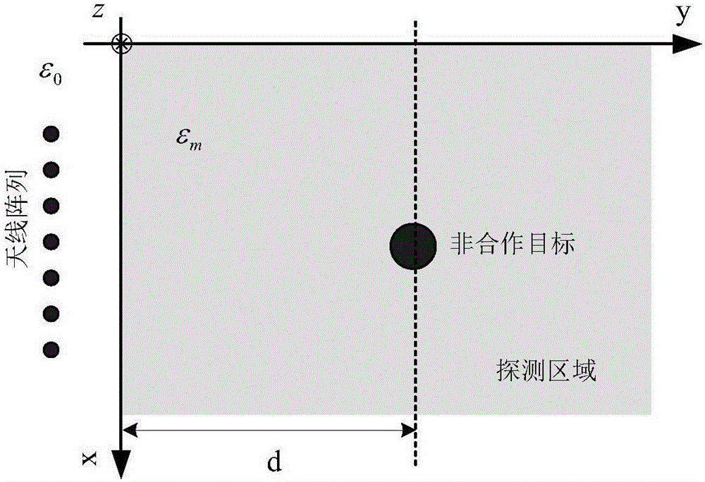
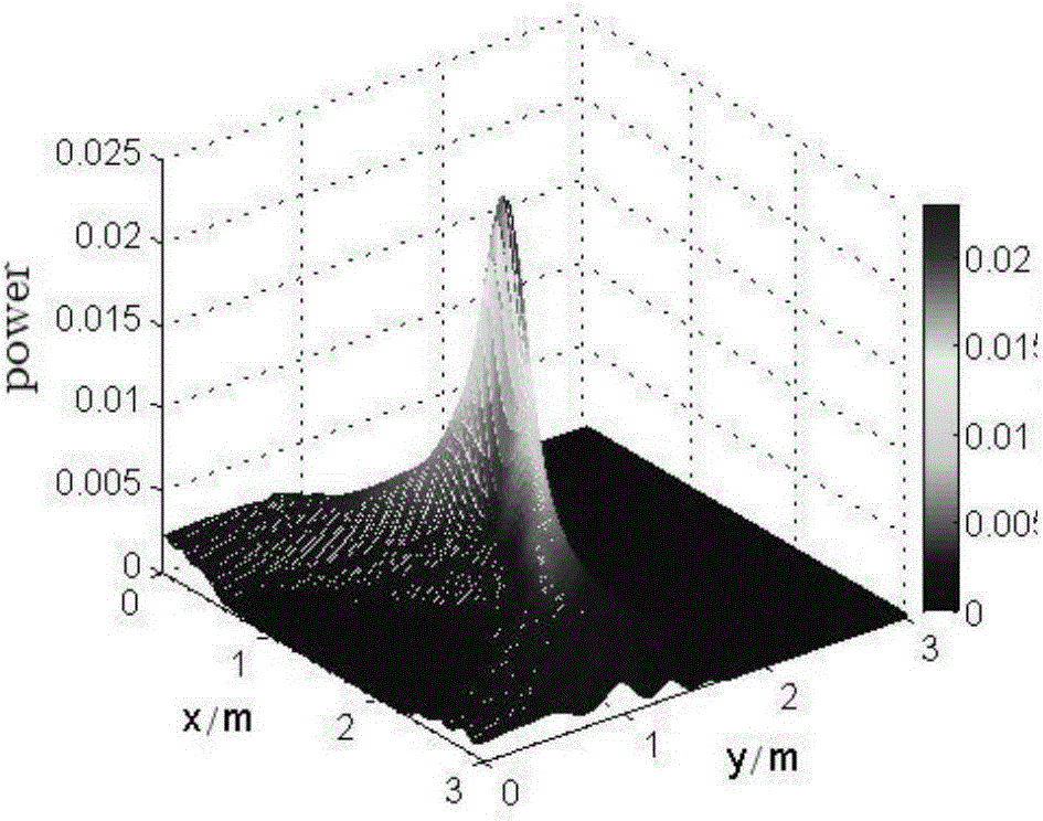
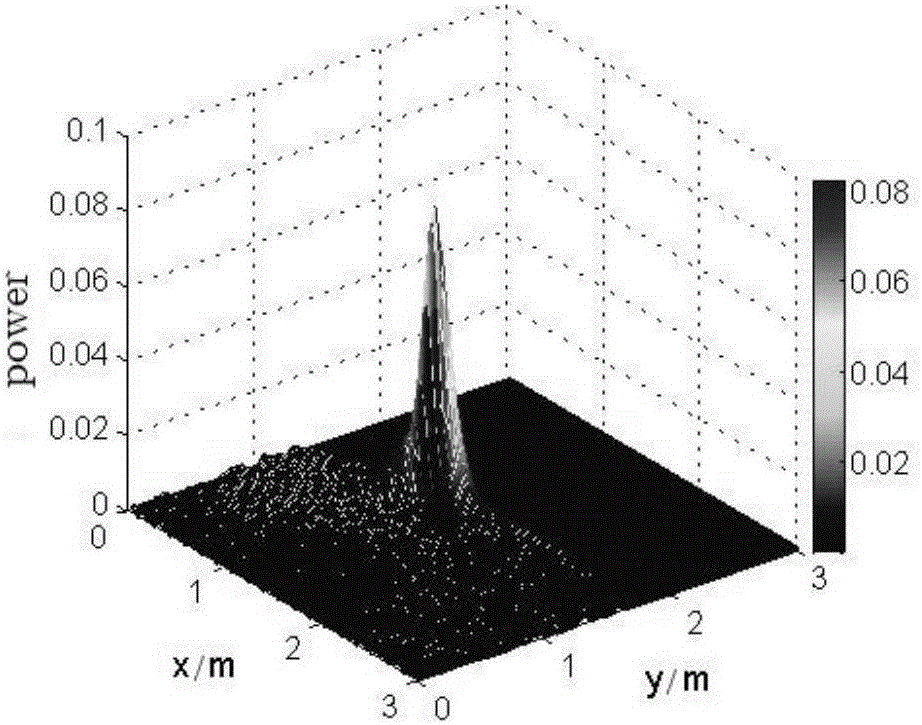

Image

  • High-efficiency and high-power microwave space power synthesis method
  • High-efficiency and high-power microwave space power synthesis method
  • High-efficiency and high-power microwave space power synthesis method

Examples


Embodiment Construction

[0014] Classical power combining refers to the in-phase superposition of multiple signals of the same frequency at the combining point. Theoretically, the amplitude of the superimposed electric field will increase linearly, while the power will increase in a quadratic relationship. When the polarization direction of each signal is the same and the time domain waveform is consistent, the maximum average power density can be obtained for multiple time domain signals.

[0015] Such as figure 1 , on one side of the detection area, set up a transceiver antenna array with N antenna units, choose any antenna to transmit the ultra-wideband pulse time-domain signal s(t), and all antenna units receive the echo signal reflected by the target. For each antenna The time domain signal k received by the unit n (t), n=1,2,...,N perform Fourier transform to obtain the frequency domain signal k n (ω),n=1,2,…,N, and then get the space-frequency polymorphic response matrix:

[0016]

[0017...


PUM


Abstract

The invention discloses a high-efficiency and high-power microwave space power synthesis method. According to the method, power synthesis of wave beams radiated by a plurality of antennas is performed in the space. The method includes the following steps that: 1) a time inversion antenna array is set at one side of a detection area, one antenna unit is arbitrarily selected to emit weak signals to detect a non-cooperative target, the main emission direction of each antenna is determined according to echoes, and the physical direction of the antenna unit is adjusted according to the main emission direction so as to be consistent with the main emission direction, and a space-frequency multi-state response matrix is built, and time inversion signals corresponding to the target are obtained; and 2) the time inversion antenna array increases power to transmit the time inversion signals obtained in the step 1) and focuses the time inversion signals at the location of the target. According to the high-efficiency and high-power microwave space power synthesis method of the invention, the time inversion algorithm is adopted to realize spatial power synthesis, and therefore, the efficiency of power synthesis is improved, and an adaptive focusing ability can be realized; and non-cooperative target detection and spatial power synthesis are integrated, and therefore, and high-power microwave space power synthesis is efficiently achieved.

Description

[0001] Technical field: [0002] The invention relates to a high-efficiency high-power microwave space power synthesis technology, which belongs to the high-power microwave field. [0003] Background technique: [0004] In recent years, ultra-broadband high-power microwaves have developed rapidly in the fields of directed energy weapons, impulse radar, power transmission, high-power microwave heating, etc. With the traction of these application requirements, how to obtain high-power microwaves through power synthesis has become an urgent technology to be solved difficulty. At present, there are two methods for high-power microwave power synthesis: one is to use solid-state power synthesis technology to obtain the corresponding combined power in the microwave channel of the equipment, but due to the limitations of high-voltage power supply and high-power devices The improvement of the output power is extremely limited; the second is to combine the beams radiated by multiple ant...

Claims


Application Information

Patent Timeline
Patent Type & Authority Applications(China)
IPC IPC(8): H01Q21/00H01Q3/00H01Q3/02H01P5/12
CPCH01Q21/00H01P5/12H01Q3/00H01Q3/02
Inventor 钟选明廖成
Owner SOUTHWEST JIAOTONG UNIV
Learn More