Method for setting parameters of SVC (supplementary damping controller)
A technology for additional damping and parameter tuning, applied in reactive power adjustment/elimination/compensation, AC network circuits, electrical components, etc., which can solve problems such as inability to directly apply, and achieve the effect of reducing workload
- Summary
- Abstract
- Description
- Claims
- Application Information
AI Technical Summary
Problems solved by technology
Method used
Image
Examples
Embodiment 1
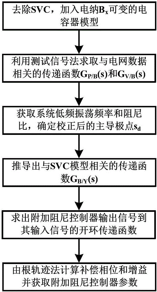
[0042] This embodiment proposes a parameter tuning method for the SVC additional damping controller, and its implementation process includes: replacing the SVC with a capacitor model with variable susceptance and finding the transfer function from the capacitor model to the input of the additional damping controller and the bus voltage The step of correcting the dominant pole of the transfer function from the obtained variable susceptance capacitor model to the input of the additional damping controller; based on the output of the additional damping controller after replacing the variable susceptance capacitor model with SVC The open-loop transfer function of the quantity to the input quantity The phase angle and amplitude at the dominant pole of the transfer function of the corrected variable susceptance capacitor model to the input quantity of the additional damping controller The step of setting the parameters of the additional damping controller. Its specific process is as ...
Embodiment 2
[0071] image 3 It is a schematic diagram of the test system with four machines and two areas. Bus 8 is the installation point of SVC, and the capacity of SVC is 200Mvar.
[0072] Remove the SVC, and add a capacitor model with variable susceptance on the bus 8. The input of the additional damping controller is assumed to be the active power on a single tie line between bus 8 and bus 9 . Using the test signal method, it can be found that:
[0073]
[0074] From this, the dominant pole of the system is obtained as S d1 =-0.024+3.13i, the system oscillation frequency is 0.5Hz, and the damping ratio is 0.77%. Choose the corrected dominant pole as S d =-0.25+3.3i.
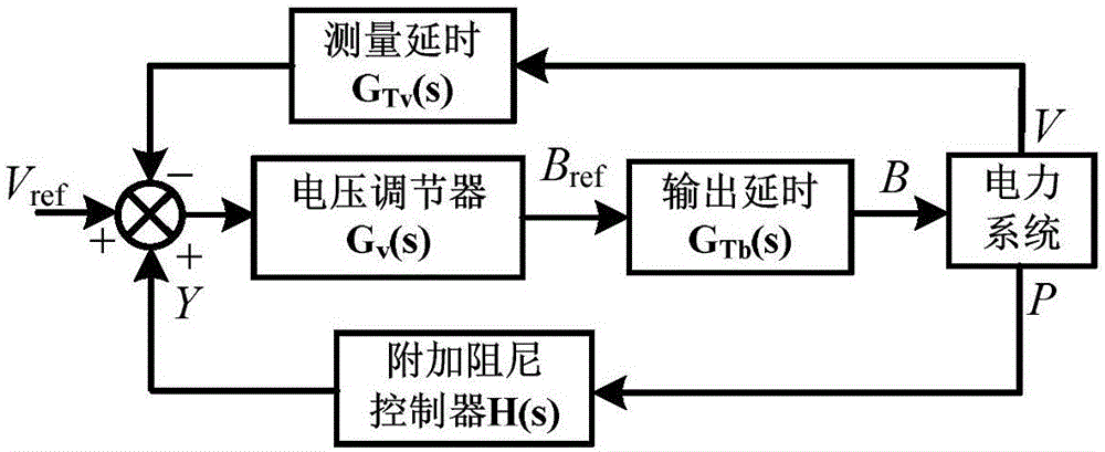
[0075] Remove the capacitor model with variable susceptance, and add SVC to bus 8. The control system of SVC adopts such as figure 2 form shown. G v (s)=K v =20, G Tv (s) and G Tb The inertial time constants of (s) are 0.02s and 0.03s, respectively. With the additional damping controller disconnected, ...
PUM
 Abstract
Description
Claims
Application Information
 - R&D
- Intellectual Property
- Life Sciences
- Materials
- Tech Scout
- Unparalleled Data Quality
- Higher Quality Content
- 60% Fewer Hallucinations
Browse by: Latest US Patents, China's latest patents, Technical Efficacy Thesaurus, Application Domain, Technology Topic, Popular Technical Reports.
© 2025 PatSnap. All rights reserved.Legal|Privacy policy|Modern Slavery Act Transparency Statement|Sitemap|About US| Contact US: help@patsnap.com


