Asynchronous motor rotor resistance and excitation inductance decoupling correction method

A technology of excitation inductance and rotor resistance, which is applied in the control of generators, motor generators, electronically commutated motors, etc., can solve problems such as failure to improve, and the impact of correction schemes on transient performance.

Active Publication Date: 2017-05-17
HEFEI UNIV OF TECH
View PDF5 Cites 3 Cited by
  • Summary
  • Abstract
  • Description
  • Claims
  • Application Information

AI Technical Summary

Problems solved by technology

In this paper, the flux linkage is obtained through the steady-state model of the voltage, and based on this, an online correction scheme for the excitation inductance and rotor time constant is designed. Although the integral problem of the flux linkage is overcome, the transient performance of the correction scheme is limited by the calculation of the flux linkage. influences
[0006] In summary, none of the existing technologies can achieve online correction of parameters and orientations.

Method used


Image

  • Asynchronous motor rotor resistance and excitation inductance decoupling correction method
  • Asynchronous motor rotor resistance and excitation inductance decoupling correction method
  • Asynchronous motor rotor resistance and excitation inductance decoupling correction method

Examples


Embodiment Construction

[0114] The present invention will be further elaborated below in conjunction with the accompanying drawings and embodiments.

[0115] In the signal acquisition part, the stator voltage vector V and the stator current vector i are obtained by sampling the stator line voltage U ab , stator line voltage U cb , Stator A-phase current i A , Stator B-phase current i B , Stator C-phase current i C , and obtained through the transformation from the three-phase stationary coordinate system to the two-phase stationary coordinate system, the actual rotor electrical angular velocity ω r It is obtained by using a photoelectric rotary encoder.

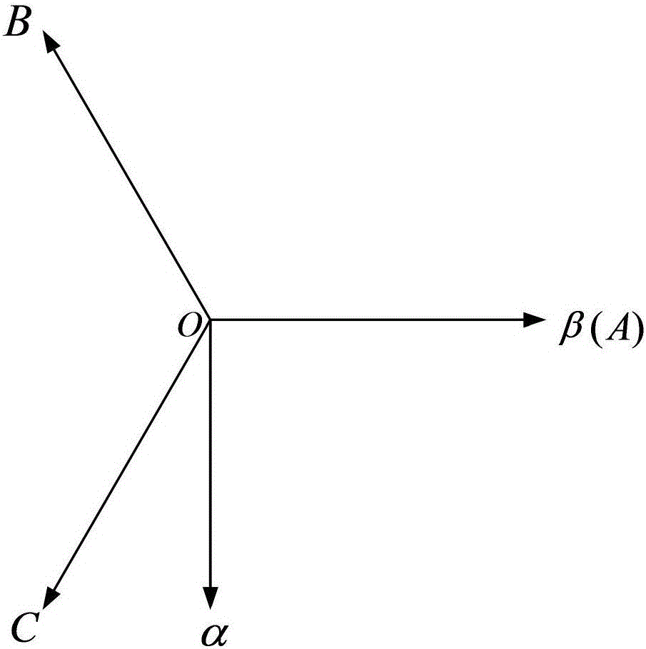
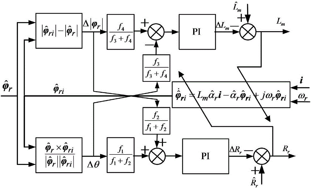
[0116] figure 1 is the static coordinate system selected in the present invention, figure 2 It is a structural block diagram of the rectification principle in the present invention. see figure 1 and figure 2 , this embodiment is carried out according to the following steps.

[0117] Step 1, collect the stator voltage vector V, stator cur...


PUM


Abstract

The invention discloses an asynchronous motor rotor resistance and excitation inductance decoupling correction method. The method comprises the steps of obtaining accurate counter electromotive force e via a high-order sliding-mode observer according to the acquired and calculated motor stator voltage vector V, stator current vector i and rotor electrical angular velocity omega r under a two-phase static coordinate system alpha beta, and establishing an asynchronous motor state space expression according to the relation between the counter electromotive force and the rotor flux, thus realizing accurate observation of a rotor flux vector phi r; obtaining a rotor flux vector calculation value which is defined in the specification according to a current flux model, then obtaining a phase difference delta theta and an amplitude difference which is defined in the specification, analyzing and deducing a correlation function of a parameter error and a flux error to obtain a weighting coefficient, correcting given rotor resistance which is defined in the specification in the system by using a decoupling correction function I which is defined in the specification, and correcting given excitation inductance in the system by using a decoupling correction function II which is defined in the specification. The method does not have the flux transient problem while solving the problem of integration of flux acquisition, and can obtain an accurate rotor time constant and realize on-line identification of the excitation inductance.

Description

technical field [0001] The invention relates to an online correction method for parameters of an asynchronous motor, in particular to a decoupling correction method for rotor resistance and excitation inductance of an asynchronous motor. Background technique [0002] Asynchronous motor is a kind of high-order multivariable nonlinear strong coupling system. The application of vector control makes it obtain the speed regulation performance of DC motor. The indirect vector control obtains the synchronous speed through the sum of the rotational speed and the slip frequency, and then obtains the orientation angle of the flux linkage. The vector control algorithm is simple, easy to implement, and has good stability, so it is a vector control scheme that is widely used. The accuracy of slip frequency calculation depends entirely on the accuracy of the rotor time constant, and this parameter is usually deviated from its nominal value due to the influence of temperature, magnetic sa...

Claims


Application Information

Patent Timeline
Patent Type & Authority Applications(China)
IPC IPC(8): H02P21/14
CPCH02P21/14
Inventor 杨淑英丁大尉李曦张兴谢震
Owner HEFEI UNIV OF TECH
Why Eureka
Try Eureka