

Overall kinetic parameter identification method based on series robot
A technology of dynamic parameters and identification methods, applied in the field of overall dynamic parameter identification based on serial robots, can solve the problems of excessive axis parameter identification accuracy errors and defects in collected data, and achieve the effect of improving reliability.
- Summary
- Abstract
- Description
- Claims
- Application Information
AI Technical Summary
Problems solved by technology
Method used
Image

Examples
Embodiment 1
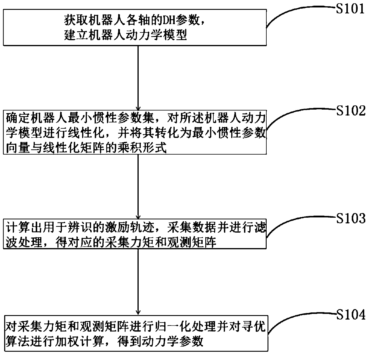
[0045] In the case of offline parameter identification, an overall dynamic parameter identification method based on serial robots includes the following steps:
[0046] Step (1): Obtain the DH parameters of each axis of the robot, and establish the conversion relationship matrix between the linkage coordinate system and each axis. Adopt Newton-Eulerian iterative method to establish the overall dynamics model of the tandem robot; the DH parameters include the rod length, rod torsion angle, joint distance and joint rotation angle of each axis of the robot;
[0047] Step (2): directly determine the minimum inertial parameter of the robot with the geometric parameters of the robot, linearize the dynamic model of the robot, and convert it into the product form of the minimum inertial parameter vector and the linearization matrix;
[0048] Step (3): Taking the condition number of the observation matrix as the optimization criterion, taking the joint angles, angular velocities, and a...
Embodiment 2
[0051] In the case of online parameter identification, an overall dynamic parameter identification method based on serial robots includes the following steps:
[0052]Step (1): Obtain the DH parameters of each axis of the robot, and establish the conversion relationship matrix between the linkage coordinate system and each axis. Adopt Newton-Eulerian iterative method to establish the overall dynamics model of the tandem robot; the DH parameters include the rod length, rod torsion angle, joint distance and joint rotation angle of each axis of the robot;
[0053] Step (2): directly determine the minimum inertial parameter of the robot with the geometric parameters of the robot, linearize the dynamic model of the robot, and convert it into the product form of the minimum inertial parameter vector and the linearization matrix;
[0054] Step (3): Taking the condition number of the observation matrix as the optimization criterion, taking the joint angles, angular velocities, and ang...
Embodiment 3
[0057] Taking the body of a six-axis series robot as an example, the scheme of robot dynamic parameter identification is described in detail.
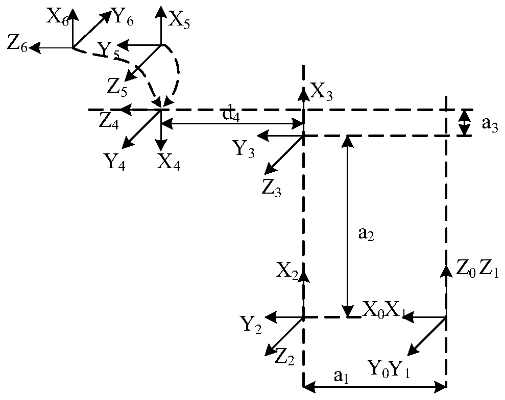
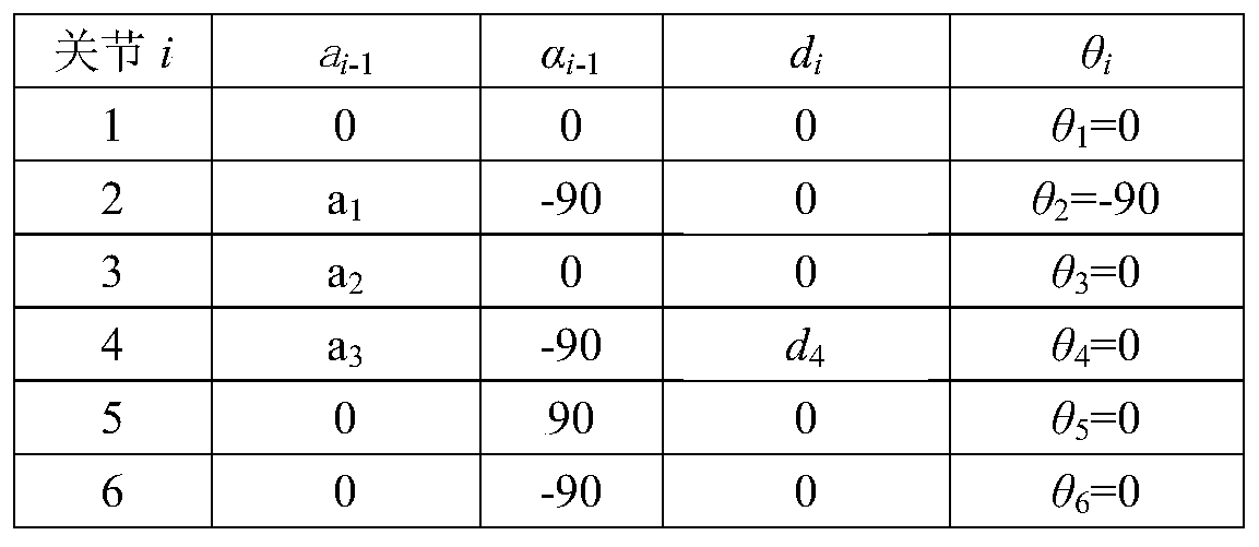
[0058] Firstly, the bar coordinate system of the serial robot is established, and the transformation matrix between each bar is established according to the DH parameters of the bar. The DH parameter includes the member length a i , member torsion angle α i , joint distance d i , joint rotation angle θ i , where i represents the joint number.
[0059] Such as figure 2 and 3 As shown, this embodiment adopts the modified DH parameters, which are different from the standard DH parameters. The rod coordinate system established by the modified DH parameters is the drive shaft coordinate system, and the conversion matrix between the coordinate systems can be calculated from the DH parameters, as shown in the formula (1) as shown:
[0060]
[0061] in is the transformation matrix between the i-1th and i-th coordinate systems, cθ ...
PUM
 Abstract
Description
Claims
Application Information