Polymer electroluminescent wire

An electroluminescent wire and polymer technology, applied in the field of polymer electroluminescent wire, can solve the problems of light energy loss, gaps not being filled, and limited improvement in the brightness of the electroluminescent wire, etc., and achieve long service life , service life, safety and environmental protection effect

Inactive Publication Date: 2017-05-17
刘三水
View PDF1 Cites 1 Cited by
  • Summary
  • Abstract
  • Description
  • Claims
  • Application Information

AI Technical Summary

Problems solved by technology

[0005] 1. Due to the different sizes of the pores formed in the luminescent layer, the particle diameter of the liquid filler used is often larger than the diameter of some pores, so some of the pores will inevitably not be filled, resulting in the light in this part of the pores. Energy loss still exists, and dark spots and black spots cannot be eliminated;
[0006] 2. Even if the gap is filled with a liquid filler, since this neutral filler will not form a new electric field around the gap to excite the fluorescent particles to emit light, the improvement of the brightness of the electroluminescent line is limited;
[0007] 3. The liquid filling can easily penetrate into the pores, and can also easily leak out or evaporate from the pores. In order to effectively prevent the loss of the liquid filling, a transparent layer needs to be coated outside the luminescent layer. The viscous insulating material is used as a barrier layer, which not only increases the complexity of the electroluminescence line, but also increases the difficulty of its manufacturing process. More importantly, the barrier layer blocks or scatters part of the luminescent layer while blocking the filling. The emitted light affects the overall brightness of the electroluminescent line

Method used


Image

  • Polymer electroluminescent wire
  • Polymer electroluminescent wire

Examples


Embodiment Construction

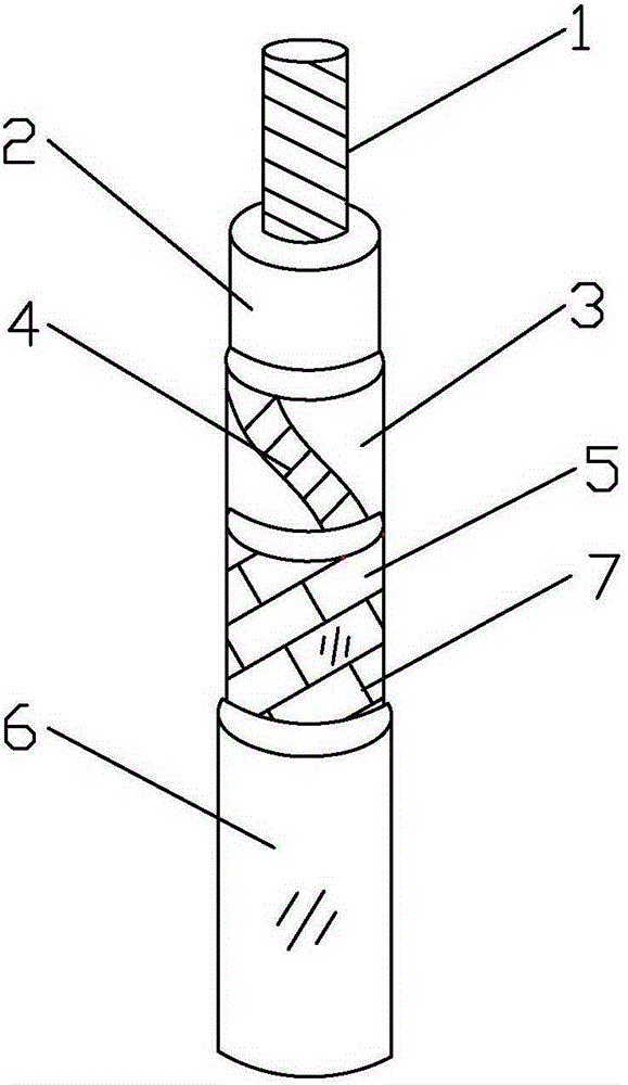
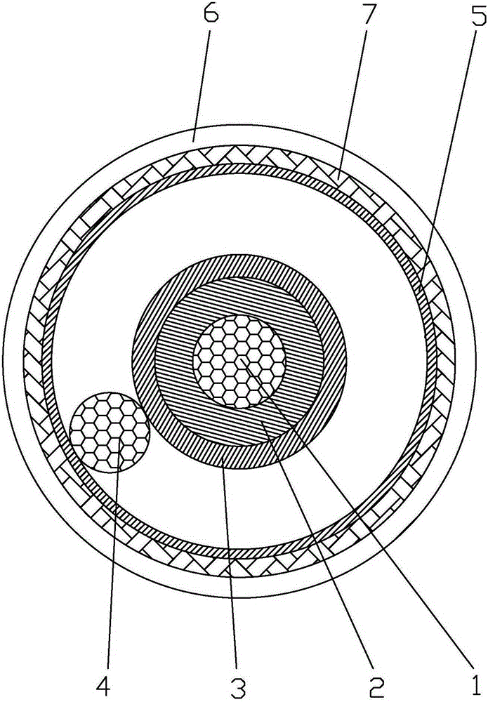
[0019] Such as figure 1 and figure 2 As shown, the polymer electroluminescent wire of the present invention includes a central electrode wire 1, a light-emitting layer 2, a light-transmitting conductive layer 3, an auxiliary electrode wire 4, a transparent polymer layer 5 and a transparent outer insulating layer 6, and the central electrode wire 1 It includes a linear conductor and is connected to the power controller. The light-emitting layer 1 is an insulating, conductive, and transparent polymer. The light-emitting layer 1 covers the central electrode line 1. The light-transmitting conductive layer 3 to cover the light-emitting layer 2, the auxiliary electrode line 4 includes a linear conductor, and is wound around the periphery of the light-transmitting conductive layer 3, and connected to the power controller, and the central electrode line 1 is connected to the auxiliary The polarity of the power line 4 is opposite to that connected to the power controller. For safety ...


PUM

PropertyMeasurementUnit
Particle sizeaaaaaaaaaa

Abstract

The invention discloses a polymer electroluminescent wire which comprises a central electrode wire, a light-emitting layer, a transparent conductive layer, an auxiliary electrode wire, a transparent polymer layer, and a transparent outer insulation layer. The central electrode wire is a linear conductor. The light-emitting layer is an insulated, conductive and transparent polymer and coats the central electrode wire. The transparent conductive layer coats the light-emitting layer. The auxiliary electrode wire is wound at the periphery of the transparent conductive layer. The transparent polymer layer coats the transparent conductive layer. The transparent outer insulation layer coats the transparent polymer layer. Since the light-emitting layer is the insulated, conductive and transparent polymer and has no hole, thus the light emitted by the electroluminescent wire is uniform and bright and is not dazzling, and the respective formation of insulated, conductive and transparent layer is avoided. In addition, polymers are used at multiple places and various protection layers are arranged, the polymer electroluminescent wire has the advantages of arbitrary bending, a long service life and safety and environmental-friendlyness, the polymer electroluminescent wire can be bent into various geometric shapes and patterns, a variety of colors can be selected, and the polymer electroluminescent wire is beautiful and novel and can be widely used for decoration.

Description

technical field [0001] The invention relates to an electroluminescent wire, in particular to a polymer electroluminescent wire using a polymer as a luminescent material. Background technique [0002] Linear luminous body is the first choice for interior advertising decoration design. In the colorful world of advertising decoration, its shining and changing colors can instantly leave an unforgettable impression on consumers. This is the purpose of advertising. Of course, it must also pass The designer's unique design concept, coupled with the use of various artistic patterns twisted and constructed by linear illuminants, according to the optimal brightness level and time control, the art is displayed in front of people, if the lighting is not used properly, or it will cause glare The glare makes people feel dizzy and uncomfortable, so even an excellent advertising design will lose its artistic style due to improper lighting, and even grotesque phenomena will appear. [0003]...

Claims


Application Information

Patent Timeline
IPC IPC(8): H05B33/12
CPCH05B33/12
Inventor 刘三水
Owner 刘三水
Why Eureka
Try Eureka