Bypass tube cleaner with slug flow control function

A technology for bypass pigging and slug flow, which is used in cleaning hollow objects, cleaning methods and utensils, chemical instruments and methods, etc., and can solve the problems of pig speed fluctuations, insufficient pushing power, and large liquid plugs. , to extend the length of the liquid plug, enhance the liquid-carrying capacity, and reduce the running resistance.

Active Publication Date: 2017-05-24
SOUTHWEST PETROLEUM UNIV
View PDF5 Cites 0 Cited by
  • Summary
  • Abstract
  • Description
  • Claims
  • Application Information

AI Technical Summary

Problems solved by technology

[0004] There are problems in the pigging process of the traditional bypass pig: during the process of removing the liquid accumulation in the pipeline, at the uphill pipe section, the front end of the traditional bypass pig has a large amount of liquid plug and a large hydrostatic pressure. Due to the gravity of the pipe itself, the power to push the ball is insufficient, the pressure at the front end of the pig is greater than that at the rear end, the pig moves in the opposite direction, the pig liquid plug moves from the front end of the pipe pig through the bypass channel to the rear end, and the pig liquid plug returns , staying in the pipeline, affecting the smooth flow of gas and causing fluctuations in the speed of the pig; the bypass rate of the traditional bypass pig (the ratio of the cross-sectional area of ​​the bypass channel opened to the cross-sectional area of ​​the pig) is a fixed value, and the cleaning The speed of the pipe can not be adjusted according to the amount of liquid plug at the front end of the pipe pig; the gas in the traditional bypass pig cannot generate vortex, which affects the effect of purging the pig liquid plug

Method used


Image

  • Bypass tube cleaner with slug flow control function
  • Bypass tube cleaner with slug flow control function
  • Bypass tube cleaner with slug flow control function

Examples


Embodiment

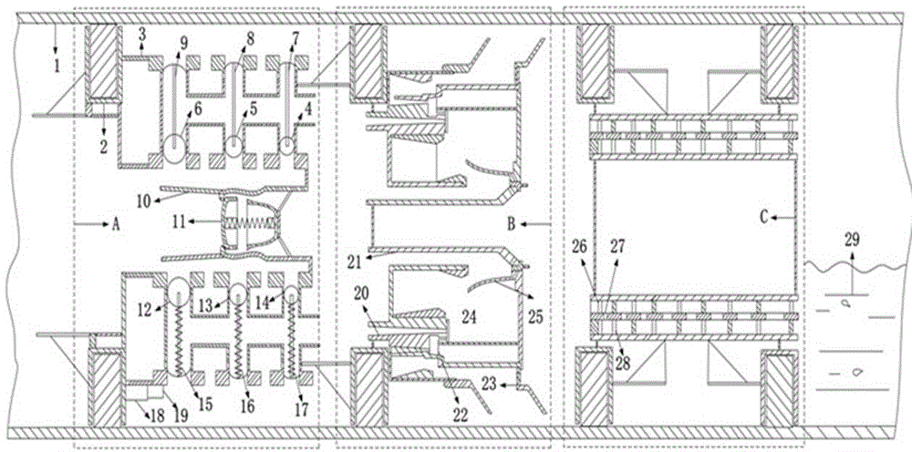
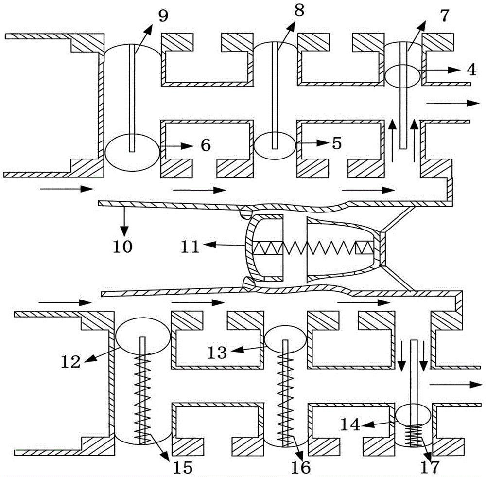
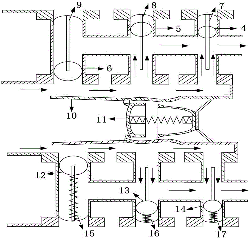
[0037] In this example, figure 1 Schematic diagram of bypass pig with slug flow control. Including pipeline inner wall 1, leather cup 2, steel frame 3, first bypass ball 4, second bypass ball 5, third bypass ball 6, first bypass rod 7, second bypass rod 8, second bypass rod Three bypass rods 9, central channel 10, central bypass ball 11, fourth bypass ball 12, fifth bypass ball 13, sixth bypass ball 14, fourth bypass rod 15, fifth bypass rod 16 , sixth bypass rod 17, electronic positioning receiver 18, electronic signal transmitter 19, tapered channel 20, high-pressure gas channel 21, atomization channel 22, gas outflow channel 23, cavity 24, one-way valve 25, the first A vortex unit 26 , a second vortex unit 27 , a third vortex unit 28 , and a pigging plug 29 .

[0038]Inside the pipeline inner wall 1 is a speed control chamber A, an atomization chamber B, and a vortex purge chamber C connected in sequence. In the speed control chamber A, a leather cup 2 is connected to a s...


PUM


Abstract

The invention relates to a bypass tube cleaner with the slug flow control function. The multiple functions of tube cleaner speed control, liquid carrying wet gas atomization, tube cleaning liquid slug vortex blowing and tube cleaning liquid slug backflow prevention are integrated; a speed control cavity is designed, a bypass channel is closed through bypass balls different in size and weight, pushing force is provided through the front and back pressure difference of the tube cleaner, the bypass balls are jacked, the bypass rate is changed, and automatic speed control over the tube cleaner is achieved; an atomization cavity is designed, one part of high-pressure gas enters a throttle channel for pressure reduction, negative pressure is formed in the atomization cavity, liquid drops in wet natural gas in the cavity are atomized, and the other part of high-pressure gas jacks open a one-way valve to enter the atomization cavity and carries atomization gas to flow out; and a vortex blowing cavity is designed, the atomization gas enters multiple vortex units to form three-stage rotational flow, the liquid slug at the front end of the tube cleaner is blown, outlets and inlets of the vortex units are arranged in a tangent manner, and backflow of the liquid slug at the front end of the tube cleaner is avoided.

Description

technical field [0001] The invention relates to a bypass pig with slug flow control and belongs to the technical field of pipeline pigging operations. Background technique [0002] In the wet gas gathering and transportation system of the gas field, the pipeline has serious liquid accumulation. The use of conventional pigs to pig the pipes results in a large change in the pipeline pressure during pigging, and the impact force of the pig liquid plug on the pipeline is large. Reaching downstream, causing flooding of downstream slug handling devices. [0003] By using traditional bypass pigs, the impact of pigging operations on normal production and pipeline operation safety is reduced, and the impact of the air flow at the rear end of the pig on the front-end liquid column is used to extend the pigging liquid plug to reach the downstream liquid plug processing device time, reducing the risk of flooding downstream liquid slug handling devices. [0004] There are problems in t...

Claims


Application Information

Patent Timeline
Patent Type & Authority Applications(China)
IPC IPC(8): B08B9/032
CPCB08B9/0327
Inventor 刘武邹宇谷雪琴
Owner SOUTHWEST PETROLEUM UNIV
Why Eureka
Try Eureka