A hot air fusion welding riveting device provided with an air inlet channel and an air exhaust channel

A technology of air inlet and exhaust ducts, applied in the field of hot air fusion welding riveting devices, which can solve the problems of high reject rate of defective products, narrow space, poor quality consistency, etc.

Active Publication Date: 2019-03-26
NINGBO SHUANGLIN MOULD CO LTD
View PDF11 Cites 0 Cited by
  • Summary
  • Abstract
  • Description
  • Claims
  • Application Information

AI Technical Summary

Problems solved by technology

[0003] There are heat conduction fusion welding riveting or hot air fusion welding riveting methods for hot-melt connection of decorative parts and plastic products; heat conduction fusion welding riveting is usually performed manually, and hot air fusion welding riveting is usually performed automatically by machines; The heat conduction fusion welding riveting of manual operation is as follows: manually insert the decorative parts into the grooves on the outside of the injection molded products, and make the welding feet of the decorative parts pass through the injection molded products to the back of the products, and use a hot electric soldering iron to Melting and flattening the welding feet, cooling and solidifying to form fusion welding riveting heads; manual work has high working intensity, manual fatigue, low efficiency, and poor quality consistency; the hot air fusion welding riveting is to embed the decorative parts into injection molding The product is placed in the outer groove, and the welding leg of the decorative part passes through the injection molded product to the back, and the welding leg is melted with scorching hot air, and then the molten welding leg is flattened by the force of the pressure head, and it is cooled and solidified Form fusion welding riveting head; hot air fusion welding riveting efficiency is high, especially suitable for automatic operation; however, hot air fusion welding riveting is performed in the cavity of cup-shaped injection molding products, refer to Figure 7 ~ Figure 10 , because the cavity space of cup-shaped injection molded products is narrow and it is difficult to dissipate heat, the hot air will also affect other structures in the cavity while melting the welding feet, resulting in a high rate of defective products. In addition, it is also difficult to dissipate heat due to the narrow space, fusion welding It is difficult to cool and solidify the head, resulting in low efficiency; as a last resort, the existing technology has to use manual work to perform thermal conduction fusion welding and riveting on the decorative parts and plastic products; Hot air welding riveting, the problems and shortcomings that it is difficult to use machines for automatic operation

Method used


Image

  • A hot air fusion welding riveting device provided with an air inlet channel and an air exhaust channel
  • A hot air fusion welding riveting device provided with an air inlet channel and an air exhaust channel
  • A hot air fusion welding riveting device provided with an air inlet channel and an air exhaust channel

Examples


Embodiment Construction

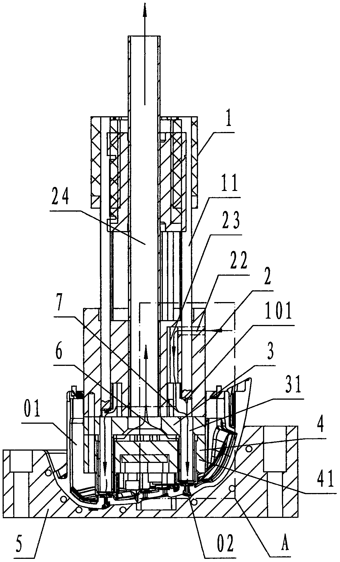
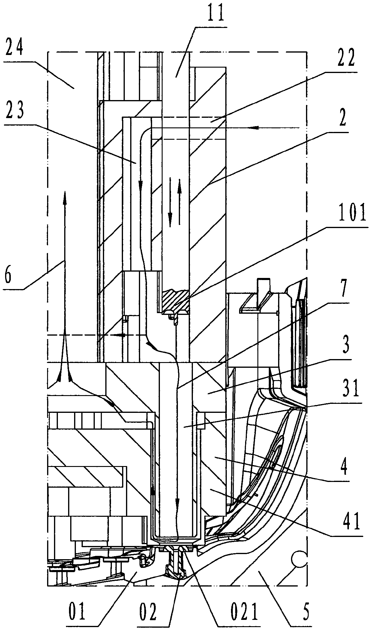
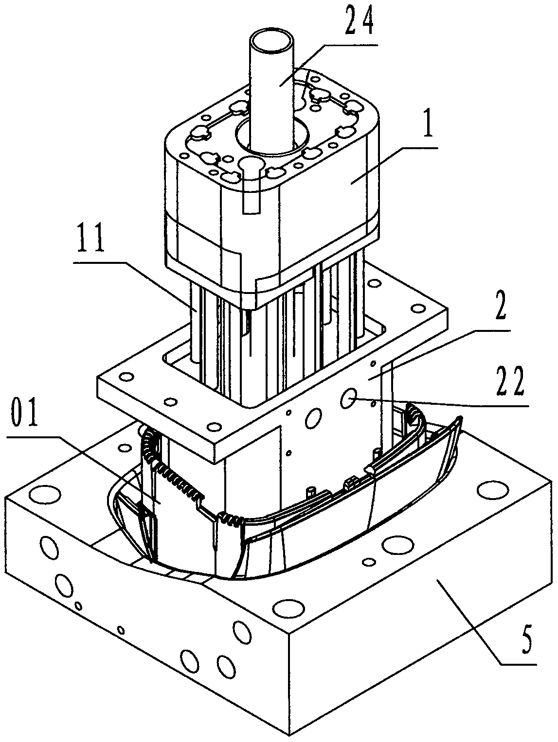
[0032] Refer to Figure 1 ~ Figure 6 , Figure 11 ~ Figure 12 , The hot-air fusion welding riveting device provided with an air inlet channel and an air outlet channel of the present invention includes a pressure rod seat 1, an air distributing seat 2, an air inlet seat 3, an exhaust air seat 4, and a positioning master 5, wherein: The strut seat 1 is a rectangular block-shaped aluminum alloy member. The center of the strut seat 1 is provided with a circular through hole in the up and down direction called the air duct hole 12; the lower periphery of the strut seat 1 is fixed with several The aluminum alloy poles that protrude downward and are parallel to each other are called the strut 11. The cross-sectional shape of the strut 11 corresponds to the top view projection shape of the welded rivet head of the finished product. The lower end surface of the strut 11 The groove provided with the shape of the fusion riveting head is called the indenter 101;

[0033] The air distributi...


PUM


Abstract

The invention discloses a hot-air fusion welding and riveting device provided with an air inlet duct and an air outlet duct. The hot-air fusion welding and riveting device comprises a pressing rod seat (1), an air distributing seat (2), an air inlet seat (3), an exhaust seat (4) and a positioning template (5). The pressing rod seat is provided with pressing rods and an air pipe hole, wherein a pressing head is arranged at the lower end of each pressing rod. The air distributing seat is provided with pressing rod guiding holes, an air inlet, an air distributing duct and an air outlet pipe. The air inlet seat is provided with air inlet pipes. The exhaust seat is provided with exhaust pipes and exhaust grooves. The air inlet duct is a channel formed by connecting the air inlet, the air distributing duct and inner cavities of the air inlet pipes, and the air outlet duct is a channel formed by connecting the gaps between the outer walls of the air inlet pipes and the inner walls of the exhaust pipes, the exhaust grooves and an inner cavity of the air outlet pipe. Through the technical scheme that the air inlet duct and the air outlet duct are used for isolating hot air from other structures of an inner cavity of a cup-shaped injection-molded product and exhausting the hot air outwards into the atmosphere, the purposes that hot-air fusion welding and riveting can be conducted in the inner cavity of the cup-shaped injection-molded product, and the device adapts to automatic operation are achieved.

Description

Technical field [0001] The invention relates to a welding device for injection-molded products, in particular to a hot-air fusion welding and riveting device provided with air inlet and exhaust channels for performing hot air fusion welding and riveting in the cavity of cup-shaped injection products. Background technique [0002] Definition: The surface of the injection molded product used to connect other objects is called the back surface, and the surface opposite to the back surface or the back surface is called the outer surface. [0003] The hot-melt connection of trims and plastic products includes thermal conduction welding and riveting; thermal conduction welding and riveting are usually performed manually, and hot-air welding and riveting are usually automated by machines; The manual thermal conduction welding and riveting process is to manually insert the trim part into the injection molding product in the outer slot, and make the welding foot of the trim part pass throug...

Claims


Application Information

Patent Timeline
Patent Type & Authority Patents(China)
IPC IPC(8): B29C65/10B29C65/26B29C35/16
CPCB29C65/10B29C65/26B29C66/006B29C66/0342B29C66/53
Inventor 陈有甫潘峰华肖荣陈达童兴浩
Owner NINGBO SHUANGLIN MOULD CO LTD
Why Eureka
Try Eureka