High-strength steel welding method

A welding method and technology of high-strength steel, applied in welding equipment, laser welding equipment, metal processing equipment, etc., can solve the problems of reduced bearing capacity of welded structures, slow cooling rate of arc welding, hidden dangers of welding structure safety, etc., and reduce the tendency of softening. , The uniformity of grain distribution is high, and the effect of heat-affected softening is low.

Active Publication Date: 2015-08-05
ZOOMLION HEAVY IND CO LTD
View PDF7 Cites 0 Cited by
  • Summary
  • Abstract
  • Description
  • Claims
  • Application Information

AI Technical Summary

Problems solved by technology

[0004] However, since the flame gun 2 is required to preheat the high-strength steel plate 1 during the high-strength steel welding process, and the cooling rate of the arc welding itself is relatively slow, therefore, in the prior art, the metal crystals in the weld seam 4 region of the high-strength steel plate 1 The grains have sufficient time to complete the three processes of recovery, recrystallization, and grain growth, resulting in coarse metal grains at the weld 4 and a decrease in the hardness of this area; Among them, weld 4 has a large melting width and a wide heat-affected zone, so the formed softening zone is obviously larger
[0005] Therefore, when the current high-strength steel welding method is used for high-strength steel welding, the heat-affected zone softening phenomenon at 4 places of the weld often occurs, and the hardness of the heat-affected zone decreases by 20% to 30%. This softening phenomenon causes local load bearing of the welded structure Decreased capacity, causing great safety hazards to welded structures with large bearing capacity

Method used


Image

  • High-strength steel welding method
  • High-strength steel welding method
  • High-strength steel welding method

Examples


Embodiment Construction

[0036] The following will clearly and completely describe the technical solutions in the embodiments of the present invention with reference to the accompanying drawings in the embodiments of the present invention. Obviously, the described embodiments are only some, not all, embodiments of the present invention. Based on the embodiments of the present invention, all other embodiments obtained by persons of ordinary skill in the art without making creative efforts belong to the protection scope of the present invention.

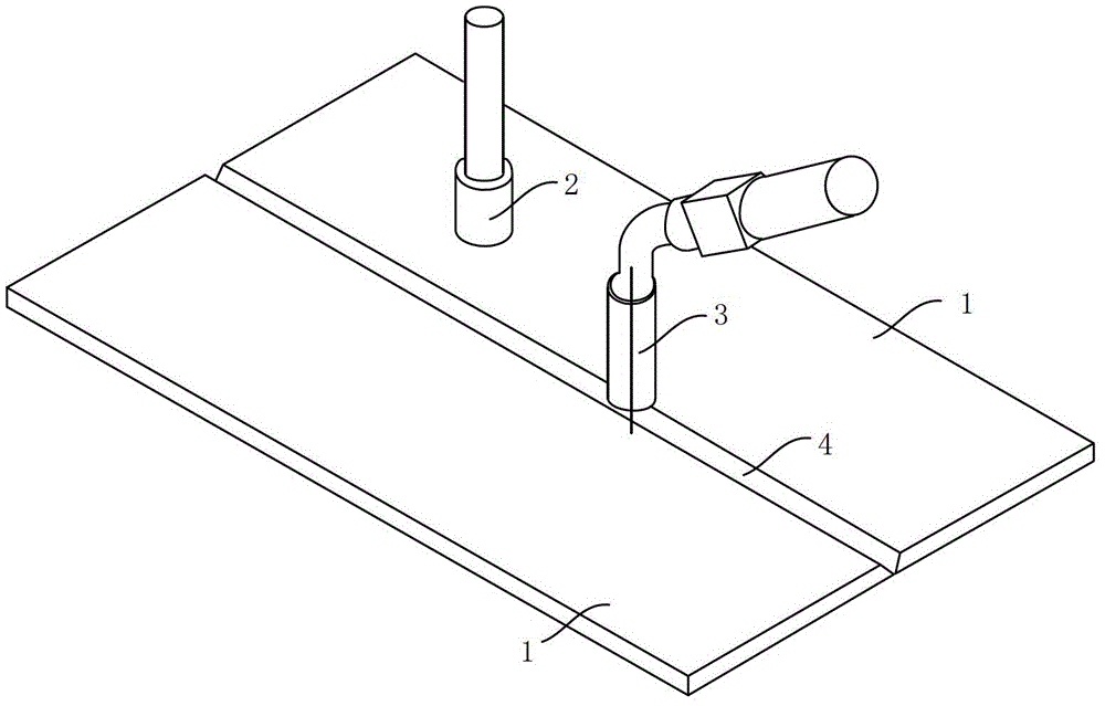
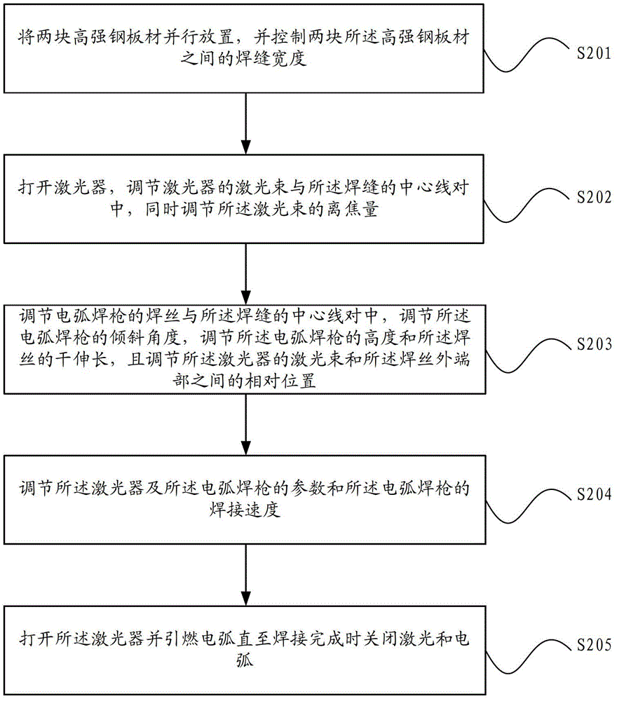
[0037] Such as figure 2 As shown, the high-strength steel welding method provided by the invention includes:

[0038] Step S201: placing two high-strength steel plates in parallel, and controlling the width of the weld between the two high-strength steel plates.

[0039] Specifically, in step S201, after the two high-strength steel plates to be welded are placed in parallel, the width of the weld between the two high-strength steel plates is adjusted accordi...


PUM

PropertyMeasurementUnit
thicknessaaaaaaaaaa
widthaaaaaaaaaa
Defocus amountaaaaaaaaaa

Abstract

The invention discloses a welding method for high-strength steel, which comprises the steps of placing two high-strength steel plates in parallel, controlling the width of a welding gap between the two high-strength steel plates, switching on a laser, regulating a laser beam of the laser to be aligned with a center line of the welding gap, regulating defocusing amount of the laser beam, regulating a welding wire of an electrical arc welding torch to be aligned with the center line of the welding gap, regulating an inclination angle and height of the electrical arc welding torch and dry extension of the welding wire, regulating relative positions between the laser beam of the laser and the outer end part of the welding wire, regulating parameters of the laser and the electrical arc welding torch and welding speed of the electrical arc welding torch, switching on the laser and igniting an electric arc, and switching off the laser and extinguishing the electric arc after the welding is finished. The welding method for the high-strength steel adopts the laser and the electric arc as heat sources, the softening phenomenon of a heat affected zone of the welding gap in a high-strength steel welding structure is reduced, and the safety of the welding structure with a stronger bearing capacity is improved.

Description

technical field [0001] The invention relates to the technical field of welding technology, in particular to a high-strength steel welding method. Background technique [0002] With the development of lightweight and large-scale welded structures, many structural parts require a substantial increase in load-bearing capacity without increasing their own weight. In order to meet their work needs, high-strength steel welded structures must be used. [0003] Such as figure 1 As shown, in the current high-strength steel welding method, when welding, it is necessary to ignite the flame gun 2 first, and after adjusting the appropriate gas flow, keep the flame gun 2 and the welding torch 3 moving at a constant speed, and the extension line of the welding wire and the high-strength steel plate When 1 intersects, ignite the arc and start welding. When the flame leaves the high-strength steel plate 1, the flame is extinguished. When the extension line of the welding wire does not inter...

Claims


Application Information

Patent Timeline
Patent Type & Authority Patents(China)
IPC IPC(8): B23K26/348
Inventor 王霄腾罗志敏任会礼付玲
Owner ZOOMLION HEAVY IND CO LTD
Why Eureka
Try Eureka