Tooling plate circular flow production line

A mobile production line and tooling board technology, which is applied in the direction of transportation and packaging, mechanical conveyors, conveyor objects, etc., to achieve the effects of saving operating time, occupying a small area, and saving costs

Active Publication Date: 2017-05-24
江苏保力自动化科技有限公司
View PDF5 Cites 2 Cited by
  • Summary
  • Abstract
  • Description
  • Claims
  • Application Information

AI Technical Summary

Problems solved by technology

[0002] At present, in order to meet the needs of operators, a tilted tooling board is required, but there is no tooling board flow production line that can be tilted during transportation in the prior art

Method used


Image

  • Tooling plate circular flow production line
  • Tooling plate circular flow production line
  • Tooling plate circular flow production line

Examples


Embodiment

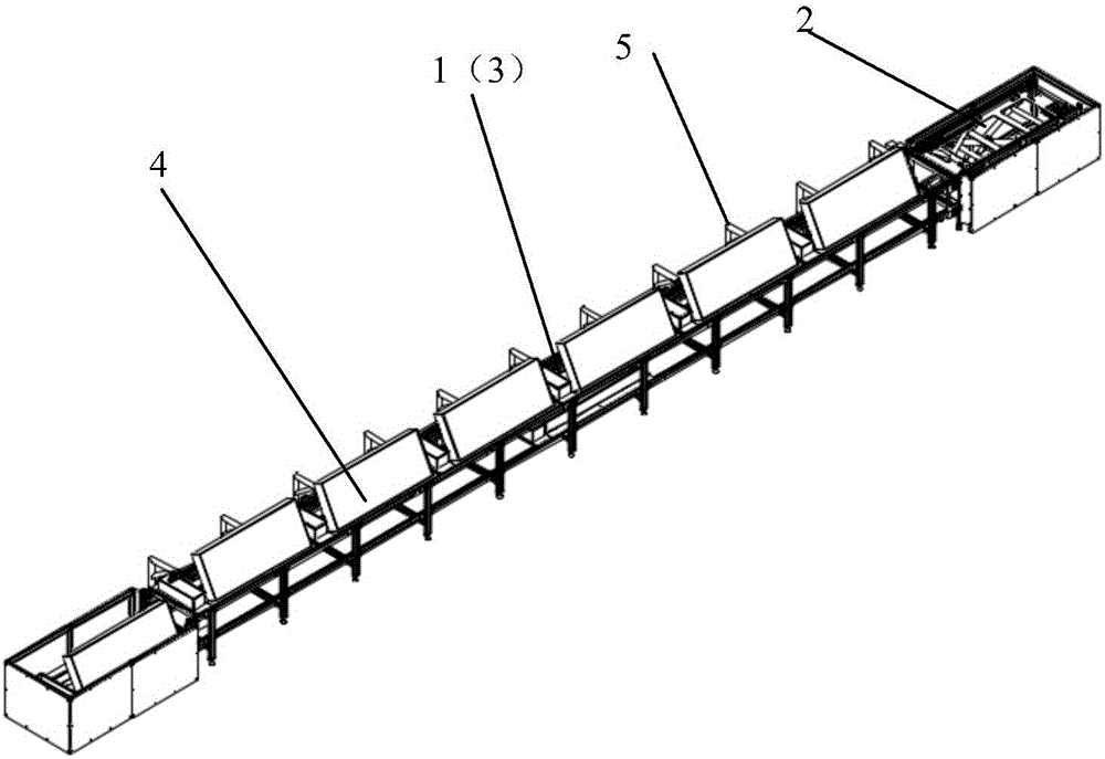
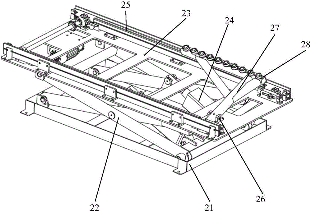
[0024] Such as figure 1 and 2 As shown, it is a three-dimensional structural schematic diagram of the tooling plate circulation production line of this embodiment.

[0025] Such as figure 1 and 3 As shown, a tooling plate circulating flow production line includes two lifting mechanisms 1 , a frame 2 , a first conveyor belt 3 , a tooling plate mechanism 4 and a cantilever guide rod 5 .

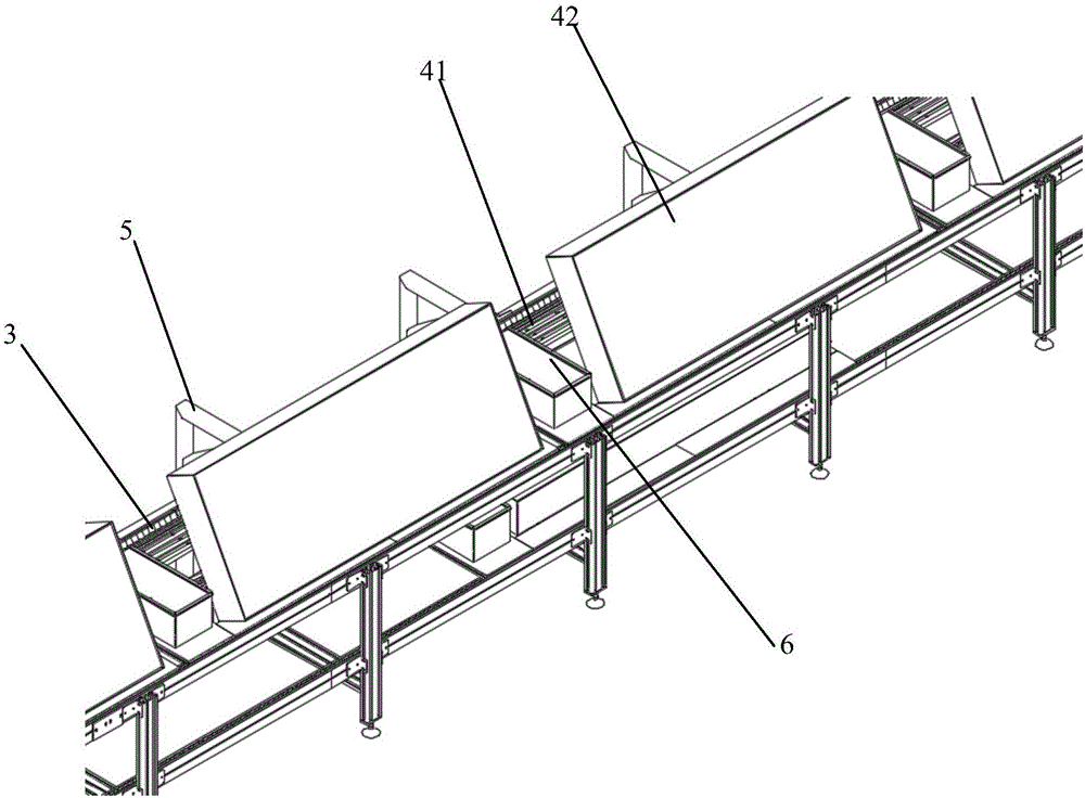
[0026] The tooling plate circulating flow production line is arranged in a "one" shape, including the lifting mechanism 1 set at both ends of the entire production line, and the first conveyor belt 3 is set through the frame 1 between the two lifting mechanisms 2, and the first conveyor belt 3 The conventional product double-speed chain conveyor in the prior art is adopted. No less than one tool frame 6 for placing operation tools is arranged horizontally on the upper surface of the frame 1 . The tooling plate mechanism 4 is arranged on the working surface of the conveyor belt, and the qua...


PUM


Abstract

The invention discloses a tooling plate circular flow production line. The technical problem that a tooling plate flow production line cannot be tilted in the transportation process in the background technology is solved. According to the technical scheme, the tooling plate circular flow production line comprises lifting mechanisms which are arranged at the two ends of the whole production line, a first conveying belt which is arranged between the two lifting mechanisms through a rack, at least one tooling plate mechanism which is arranged on the working face of the conveying belt, and at least one cantilever guide rod which is arranged on the rack and used for supporting a tilted tooling frame rolled over. The tooling plate circular flow production line has the advantages that circulation in the up-down vertical direction is adopted, and the production line only occupies half of the land of a similar production line; and the tooling plate circular flow production line is compact in land occupation, and circulation without power failures is realized.

Description

technical field [0001] The invention relates to a circulating flow production line of tooling boards. Background technique [0002] At present, in order to meet the needs of operators, a tilted tooling board is required, but there is no tooling board flow production line that can be tilted during the conveying process in the prior art. Contents of the invention [0003] The technical problem to be solved by the present invention is to solve the technical problem in the background technology that there is no tooling board flow production line that can be tilted during the conveying process. [0004] The design idea of ​​the present invention is to develop a tooling plate circulating flow production line that can be opened at a certain angle to be inclined and set at a certain angle in a specific occasion, and keep a certain angle to move forward. [0005] In order to solve the problems of the technologies described above, the technical solution adopted in the present inven...

Claims


Application Information

Patent Timeline
Patent Type & Authority Applications(China)
IPC IPC(8): B65G47/248B65G37/00
CPCB65G37/00B65G47/248B65G2201/022
Inventor 刘斌陆锦林徐远
Owner 江苏保力自动化科技有限公司
Why Eureka
Try Eureka