
Double-body granary with self-rotating grain distributors

A grain distributor and spin-type technology, which is applied in the field of granary structure design, can solve the problems of small porosity, poor effect and high cost of grain piles, and achieve the effect of reducing the overall occupied space, saving the driving motor and having a reasonable structure.

Inactive Publication Date: 2017-05-24
申清章
View PDF7 Cites 0 Cited by
  • Summary
  • Abstract
  • Description
  • Claims
  • Application Information

AI Technical Summary

Problems solved by technology

[0002] Modern grain logistics requires fast grain entry and exit. At present, modern large-scale modern granaries, mainly shallow round silos and vertical silos, have the advantages of relatively small footprint, large storage capacity, and high degree of mechanization, which greatly speeds up the grain transportation. The speed of entering and exiting the silo; however, because the shallow round silo and the vertical silo have only one grain inlet at the top, and the grain inlet is tens of meters away from the ground, when the grain is fed, due to the different physical properties of the impurities and grain particles, it will cause serious grain automatic failure. The grading phenomenon leads to the mineral impurity area, especially the impurity cylinder area at the center of the circle, and the light impurities float to the surroundings to form an annular light impurity area around, especially the impurity cylinder area at the center of the circle. Due to a large amount of dust and broken grains, the grain The pile porosity is very small, which affects grain ventilation, cooling, precipitation, fumigation and insecticide, and impurities carry a large number of microorganisms, which seriously affects the safe storage of grain
This area is often hot, moldy, and agglomerated during grain storage, which seriously affects the safety of grain storage and increases the workload of grain storage
In order to reduce the accumulation of impurities caused by automatic grading caused by excessive concentration of grain from one grain inlet, certain measures are also taken at present, such as setting a conical hood under the grain inlet, so that the grain flowing into the grain inlet is along the slope of the conical hood. Move a certain distance outside to disperse the concentrated falling of the grain, but this method can only change the grain into a ring from a point, and there will still be an impurity ring area under the conical mask mouth, which cannot effectively eliminate the accumulation of impurities , due to the poor effect, it is rarely used at present, and has not been promoted so far
In addition, most of the current traditional granaries adopt a single-body design, which can only store one kind of grain at the same time, and has a single function
There are also some granaries that adopt a double-body design, but use two separate sets of unloading devices to unload grain separately, resulting in the disadvantages of occupying a large area and high cost

Method used


Image

  • Double-body granary with self-rotating grain distributors
  • Double-body granary with self-rotating grain distributors
  • Double-body granary with self-rotating grain distributors

Examples


Embodiment 1)

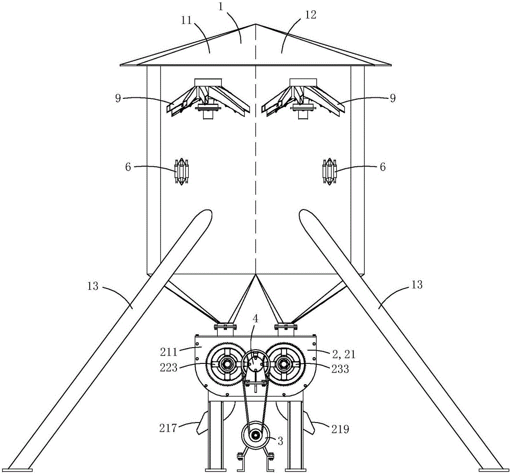
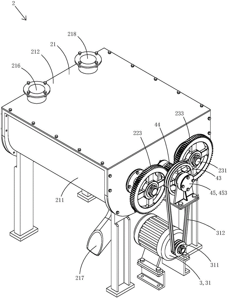
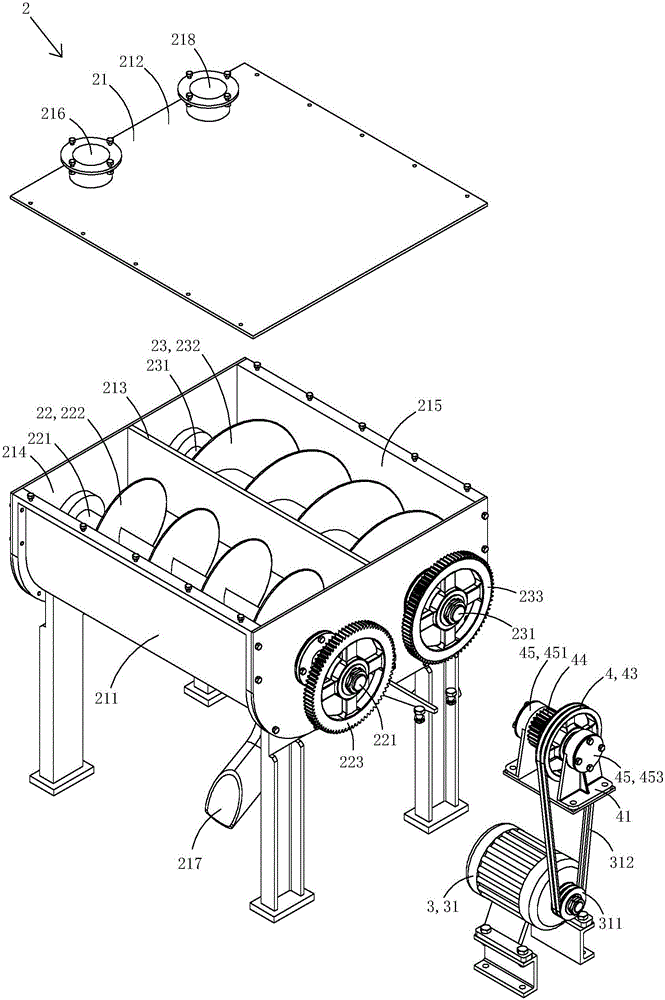
[0032] Figure 1 to Figure 2 5 shows the first embodiment of the present invention.

[0033] This embodiment is a dual-body granary with a spin-type grain distributor, see Figure 1 to Figure 7 Shown, comprise double-body warehouse 1 and be arranged on the grain unloading device 2 below double-body warehouse.

[0034] The double-body warehouse 1 has a first warehouse 11 and a second warehouse 12 arranged side by side. The bottom of the first warehouse is conical, and the center of the bottom has a first outlet; the bottom of the second warehouse is also conical, and the bottom of the second warehouse is conical. There is a second outlet in the center. In this embodiment, four supporting pillars 13 are arranged at the lower part of the double-body warehouse, and the double-body warehouse stands on the ground through the four supporting pillars. In practice, it is also possible not to support the pillars, but directly fix the double-body warehouse on the wall or on the carrie...

Embodiment 2)

[0085] Figure 21 to Figure 2 5 shows a second embodiment of the present invention.

[0086] This embodiment is basically the same as Embodiment 1, the difference is: see Figure 21 to Figure 2 As shown in 5, the side end of the limit stop platform in the present embodiment is closer to the pulley, the side end of the pulley near the limit stop platform and both sides of the clutch transmission gear are provided with gear teeth 5 , each tooth is provided with a bearing surface 51 and a guide surface 52, and each guide surface is an arc surface. When the clutch transmission gear translates towards the direction of the limit stop, the thrust surface of the gear teeth of the clutch transmission gear finally abuts against the thrust surface of the gear teeth of the limit stop; when the clutch transmission gear translates towards the direction of the pulley, the clutch The thrust bearing surface of the gear teeth of the transmission gear finally abuts against the thrust bearing s...


PUM


Abstract

The invention discloses a double-body granary with self-rotating grain distributors. The double-body granary comprises a double-body warehouse and a grain unloading device; the double-body warehouse has a first warehouse and a second warehouse; the self-rotating grain distributors are respectively arranged in the first warehouse and the second warehouse; the grain unloading device includes a box body with a first grain unloading cavity and a second grain unloading cavity, a first auger for unloading grains stored in the first grain unloading cavity, a second auger for unloading the grains stored in the second grain unloading cavity, and a driving device for driving the first auger and the second auger to rotate; the first auger includes a first rotating shaft, a first spiral plate and a first driven gear; the second auger includes a second rotating shaft, a second spiral plate and a second driven gear; the driving device includes a driving motor and a clutch linkage device; the clutch linkage device includes a frame body, a transmission shaft, a clutch transmission gear and a belt wheel; the transmission shaft is provided with an external thread part; and the clutch transmission gear is screwed on the external thread part of the transmission shaft. The double-body granary is more uniform in grain distribution, can store two types of grains, and is lower in manufacturing cost.

Description

technical field [0001] The invention belongs to the technical field of granary structure design, and in particular relates to a double-body granary with a spin-type grain distributor. Background technique [0002] Modern grain logistics requires fast grain entry and exit. At present, modern large-scale modern granaries, mainly shallow round silos and vertical silos, have the advantages of relatively small footprint, large storage capacity, and high degree of mechanization, which greatly speeds up the grain transportation. The speed of entering and exiting the silo; however, because the shallow round silo and the vertical silo have only one grain inlet at the top, and the grain inlet is tens of meters away from the ground, when the grain is fed, due to the different physical properties of the impurities and grain particles, it will cause serious grain automatic failure. The grading phenomenon leads to the mineral impurity area, especially the impurity cylinder area at the cen...

Claims


Application Information

Patent Timeline
IPC IPC(8): B65G65/46B65G69/04
CPCB65G65/46B65G69/0458
Inventor 申清章
Owner 申清章
Learn More