Floating type concentrated heat saline-water desalination device

A hot salt water, floating technology, applied in the field of salt water desalination, can solve the problems of limited desalinated water, difficult transportation, difficult collection, etc., to achieve the effect of increasing water supply efficiency, saving storage space, and saving land resources

Inactive Publication Date: 2017-05-24
ZHEJIANG UNIV
View PDF4 Cites 1 Cited by
  • Summary
  • Abstract
  • Description
  • Claims
  • Application Information

AI Technical Summary

Problems solved by technology

[0004] 1. The photothermal desalination device is generally made of glass, which is expensive, heavy, occupies a large area, and is easily broken, so it is not suitable for large-scale production and use
[0005] 2. The temperature difference between the inside and outside of the tilted glass of the existing desalination device is small, so most of the water vapor cannot be condensed and collected, the desalinated water produced is limited, and the desalination efficiency is not high
[0006] 3. The saline-alkali water in the water-scarce areas of western my country mainly exists in the form of salt lakes and agricultural salt drainage ditches. The saline-alkali water is scattered and difficult to collect. However, the existing desalination device is a glass structure, which is heavy and difficult to transport. The saline-alkali water is transported through pipelines And the cost is too high, resulting in a lot of saline-alkali water that cannot be desalinated and utilized
[0007] 4. Injecting saline-alkali water into the desalination device requires a water pump to provide water head, which increases the energy consumption and economic cost of the device

Method used


Image

  • Floating type concentrated heat saline-water desalination device
  • Floating type concentrated heat saline-water desalination device
  • Floating type concentrated heat saline-water desalination device

Examples


Embodiment

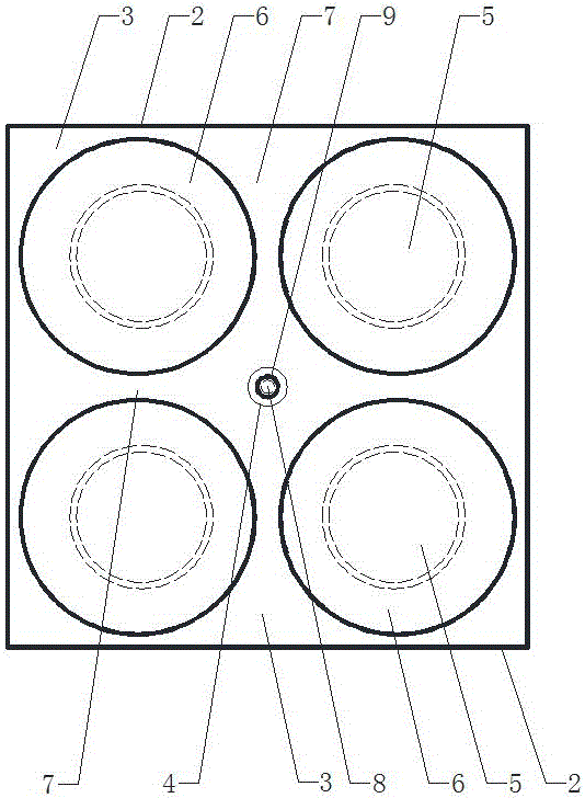
[0041] When the device is in an uninflated state, such as figure 2 As shown, plug the bottom plug 4, and inflate the device through the external port on the top of the central hose 8.

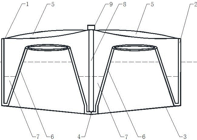
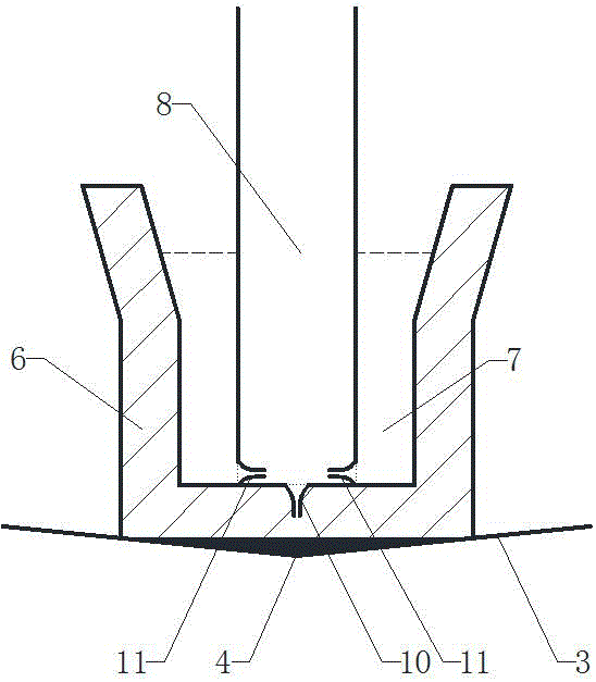
[0042] When the device is inflated, the bottom end of the central hose is partially enlarged as image 3 As shown, the inflation valve 10 of the central hose 8 leading to the buoy air bag 6 is opened, and air is charged into the air bag through the inflation valve 10; Such as figure 1 As shown, the inflation state of the device can be judged by observing the shape of the central hose 8, and when the central hose 8 is substantially straightened, the inflation is stopped.

[0043] Evaporation process: push the air-filled device into the saline water (sea water, salt lake, agricultural salt drainage ditch), due to the device's own buoyancy and the gravity of the aggravated bottom cover, the device keeps floating on the water surface. Due to the principle of the connector, the saline water will...


PUM


Abstract

The invention discloses a floating type concentrated heat saline-water desalination device, which mainly comprise an upper wall, side wall air bags, a bottom wall, float bowl air bags and a central hose, wherein the device can keep afloat after the side wall air bags and the float bowl air bags are inflated through the central hose; the float bowl air bags surround to form a plurality of regularly distributed evaporation units; each evaporation unit is in a circular truncated cone shape; the bottom parts of the evaporation units are the bottom wall; table surfaces of the evaporation units are hollowed; convex lenses one-to-one corresponding to the evaporation units are arranged on the upper wall; a principal optic axis of each convex lens points to the corresponding evaporation unit, so that the evaporation of saline water in the evaporation units is accelerated; containers formed by the float bowl air bags and the side wall air bags and containers formed between the float bowl air bags are fresh water collecting chambers. The floating type concentrated heat saline-water desalination device provided by the invention is used for desalinating saline-alkaline water, is simple in structure, not easy to damage, low in cost, high in efficiency, and clean and environmental-friendly, can be used in inland and coastal water-deficient region, and has a wide application prospect.

Description

technical field [0001] The invention relates to a brine desalination device, in particular to a floating concentrated heat brine desalination device. Background technique [0002] With the development of my country's economy, water resources are increasingly becoming a scarce resource. Not only in the inland hinterland where rainfall is scarce, many densely populated coastal areas are also facing water shortages. With the increasing cost of long-distance water diversion, it is of great significance to the sustainable development of the national economy to use nearby saline-alkali water (seawater, salt lakes, agricultural salt drainage ditches) to desalinate for industrial, agricultural and residential use. Among the many desalination technologies, solar thermal energy desalination technology has been attracting attention due to its low price, cleanness and environmental protection. However, the existing photothermal energy desalination technology has low efficiency and poo...

Claims


Application Information

Patent Timeline
Patent Type & Authority Applications(China)
IPC IPC(8): C02F1/14
CPCC02F1/14C02F2103/08Y02A20/142Y02A20/212Y02A20/124
Inventor 孙志林纪汗青方诗标许丹
Owner ZHEJIANG UNIV
Why Eureka
Try Eureka