
Latex paint waste water pre-treating device

A pretreatment device, latex paint technology, applied in water/sewage treatment, water/sewage multi-stage treatment, flotation water/sewage treatment, etc., to improve biodegradability, prevent polarization or scaling, and sewage treatment efficiency high effect

Pending Publication Date: 2017-05-24
SHAANXI RES DESIGN INST OF PETROLEUM CHEM IND
View PDF7 Cites 2 Cited by
  • Summary
  • Abstract
  • Description
  • Claims
  • Application Information

AI Technical Summary

Problems solved by technology

[0004] The technical problem to be solved by the present invention is to overcome the shortcomings of the existing latex paint wastewater treatment device, and provide a latex paint wastewater pretreatment device that is easy to replace, high in processing efficiency, low in power consumption, and easy to operate

Method used


Image

  • Latex paint waste water pre-treating device
  • Latex paint waste water pre-treating device
  • Latex paint waste water pre-treating device

Examples


Embodiment 1

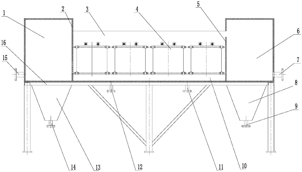
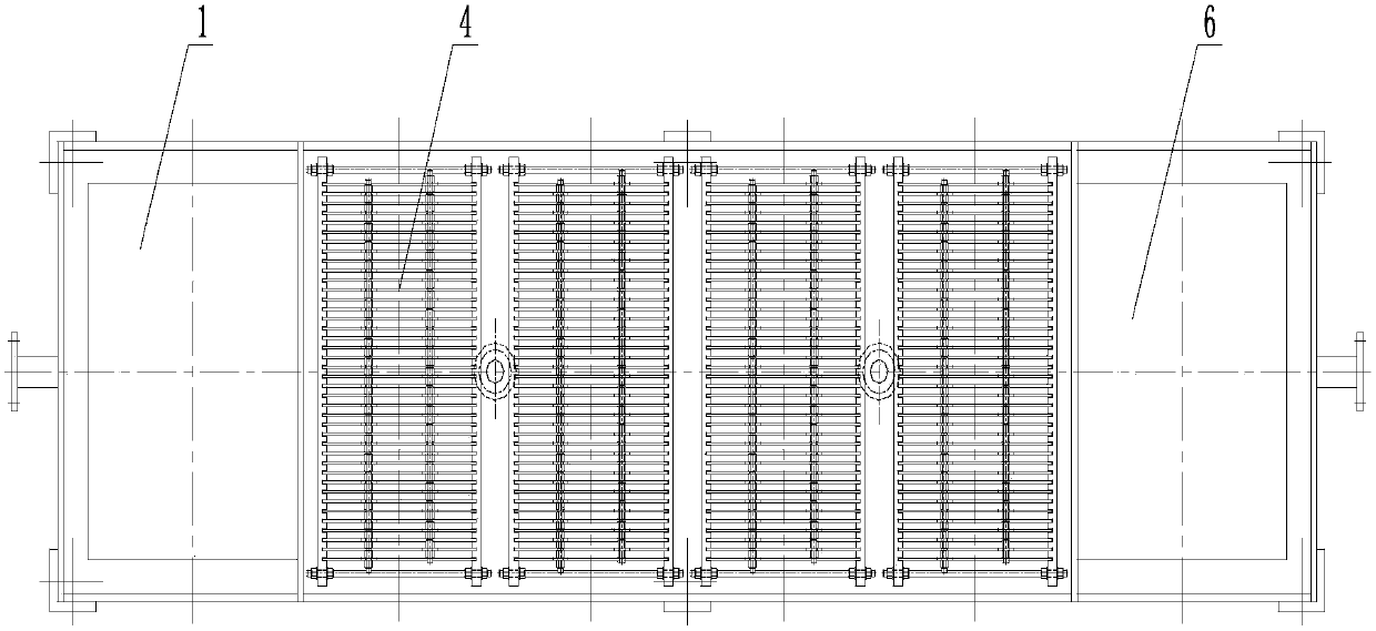
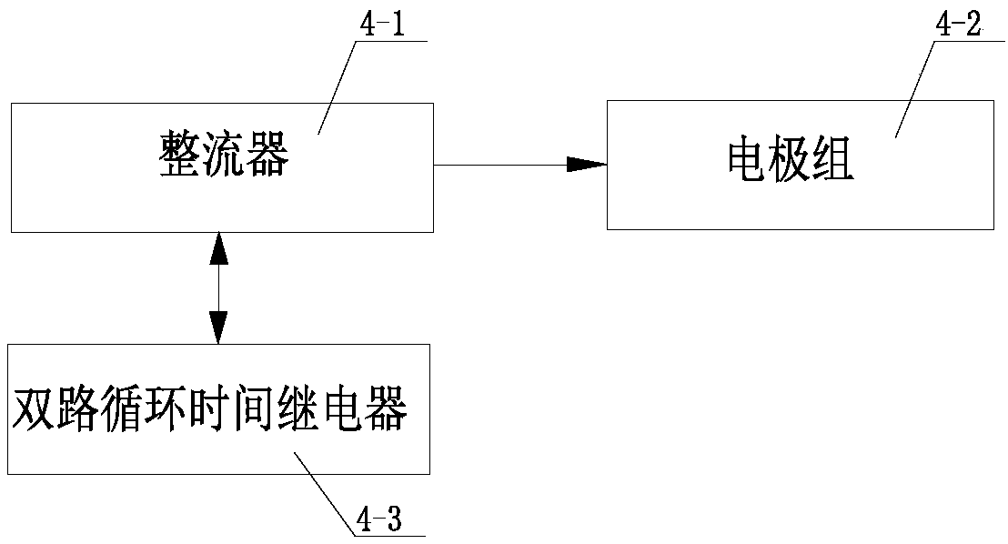
[0027] exist figure 1 , 2 Among them, the latex paint wastewater pretreatment device of the present embodiment consists of a water inlet tank 1, a first dividing plate 2, a flocculation reaction tank 3, an electrocoagulation reactor 4, a second dividing plate 5, a water outlet tank 6, an outlet pipe 7, two Secondary settling tank 8, fourth blowdown pipe 9, electroflocculation reactor base 10, third blowdown pipe 11, second blowdown pipe 12, primary settling tank 13, first blowdown pipe 14, water inlet pipe 15, and support 16 are connected.

[0028] A water inlet tank 1, a flocculation reaction tank 3, and a water outlet tank 6 are sequentially installed on the bracket 16, the water inlet tank 1, the flocculation reaction tank 3 and the water outlet tank 6 are connected as one, and a water inlet pipe 15 is installed on one side of the water inlet tank 1, A first partition 2 is installed between the other side of the water inlet tank 1 and the flocculation reaction tank 3, and ...

Embodiment 2

[0034] In this embodiment, the water inlet tank 1, the flocculation reaction tank 3, and the water outlet tank 6 are sequentially installed on the support 16, the water inlet tank 1, the flocculation reaction tank 3 and the water outlet tank 6 are connected as one, and the water inlet tank 1 and the flocculation reaction tank The first partition 2 is installed between the tanks 3, and the middle and lower parts of the first partition are processed with evenly distributed water distribution holes, the aperture of the water distribution holes is 10mm, and the electroflocculation reactor base 10 in the flocculation reaction tank 3 is installed with The electrocoagulation reactor 4, the number of electrode groups 4-2 of the electrocoagulation reactor 4 is 1 group, and the two ends of the electrode group 4-2 are insulated under the framework 4-2-4 with insulating screws 4-2- 4 Fixedly connected to form the base of the electrode plate, the inner sides of the two lower insulating fram...

Embodiment 3

[0036] In this embodiment, the water inlet tank 1, the flocculation reaction tank 3, and the water outlet tank 6 are sequentially installed on the support 16, the water inlet tank 1, the flocculation reaction tank 3 and the water outlet tank 6 are connected as one, and the water inlet tank 1 and the flocculation reaction tank The first partition 2 is installed between the tanks 3, and the middle and lower parts of the first partition are processed with evenly distributed water distribution holes. The aperture of the water distribution holes is 30 mm. The electroflocculation reactor 4, the number of electrode groups 4-2 of the electroflocculation reactor 4 is 5 groups, and the two ends of the electrode group 4-2 are insulated with insulating screws 4-2-4. 4 Fixedly connected to form the base of the electrode plate, the inner sides of the two lower insulating frames 4-2-4 are processed with 20 L-shaped slots at equal intervals along the length direction, the first electrode plate...


PUM

PropertyMeasurementUnit
Thicknessaaaaaaaaaa

Abstract

Provided is a latex paint waste water pre-treating device. A water inlet tank, a flocculation reaction tank and a water outlet tank are sequentially arranged on a support, the water inlet tank is communicated with the flocculation reaction tank, the flocculation reaction tank is communicated with the water outlet tank, the water inlet tank, the flocculation reaction tank and the water outlet tank are connected to form a whole, a water inlet pipe is arranged on one side of the water inlet tank, a preliminary precipitation tank is arranged at the bottom, a first blow-off pipe is arranged at the lower end of the preliminary precipitation tank, a second blow-off pipe and a third blow-off pipe are arranged at the bottom of the flocculation reaction tank, an electric flocculation reactor is arranged in the flocculation reaction tank, a water outlet pipe is arranged on one side of the water outlet tank, a secondary precipitation tank is arranged at the bottom, a fourth blow-off pipe is arranged at the lower end of the secondary precipitation tank, and the water inlet tank, the flocculation reaction tank and the water outlet tank are insulator. The problem of latex paint wastewater treatment is solved, latex paint wastewater can be demulsified and flocculated without agents, the suspended matter and pollutant disposal efficiency is high, and the biodegradability of the latex paint wastewater is greatly improved.

Description

technical field [0001] The invention belongs to the technical field of sewage treatment equipment or devices, and in particular relates to a latex paint wastewater pretreatment device. Background technique [0002] In recent years, the real estate construction industry has become a major pillar industry that stimulates the national economy, and the consumption of latex paint has also increased year by year. Therefore, latex companies of various sizes are blooming all over the country. Due to the backwardness of the production process and the weak awareness of environmental protection, the treatment of latex paint production wastewater has not been paid attention to by the application. With the introduction of my country's "Water Ten Measures", the requirements for environmental protection are getting higher and higher, and the problem of sewage treatment and discharge has become a top priority. [0003] Latex paint wastewater is mainly produced when washing production equip...

Claims


Application Information

Patent Timeline
IPC IPC(8): C02F9/06C02F1/463C02F1/465
CPCC02F1/46104C02F1/463C02F1/465C02F2001/007C02F2201/46125C02F2201/4614
Inventor 张国辉杨鸿鹰王丽莉王玲燕任蕊张玉娟
Owner SHAANXI RES DESIGN INST OF PETROLEUM CHEM IND
Learn More