Quenching robot

A robot and quenching tank technology, applied in the field of heat treatment, can solve the problems of large dimensional changes and easy deformation, and achieve the effect of changing the cooling speed, reducing labor intensity and stabilizing the quality of quenching

Inactive Publication Date: 2017-05-24
HENAN UNIV OF SCI & TECH
View PDF3 Cites 2 Cited by
  • Summary
  • Abstract
  • Description
  • Claims
  • Application Information

AI Technical Summary

Problems solved by technology

Even if these quenching methods are used, for some workpieces with special structures, large dimensional changes, easy deformation, etc. or special requirements such as overall heating and partial quenching, manual operation is required to achieve the purpose of quenching

Method used


Image

  • Quenching robot
  • Quenching robot

Examples


Embodiment 1

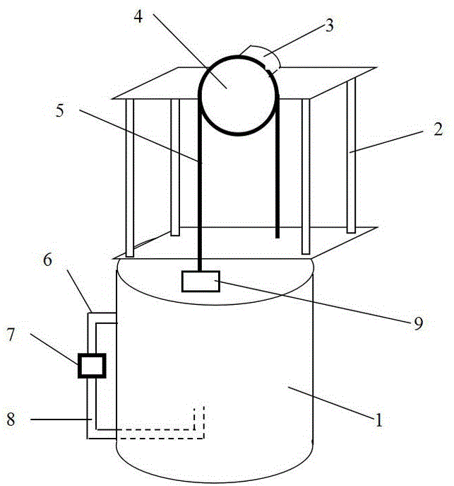
[0014] Such as figure 1 Shown: a kind of quenching robot, comprises the quenching tank 1 that is used to store quenching medium and a lifting mechanism that is used to drive quenched workpiece 9 lifting, the upper end opening of described quenching tank 1 is provided with, and quenching tank 1 is also provided with The inlet pipe 6 and the outlet pipe 8, the outlet pipe 8 is located below the inlet pipe 6, and a pipeline booster pump 7 for pressurizing the quenching medium is arranged between the outlet pipe 8 and the inlet pipe 6, and the lifting mechanism passes through the bracket 2 Set on one side of the quenching tank 1, the lifting mechanism includes a motor 3, a sprocket 4 connected to the output end of the motor 3 and a chain 5 matched with the sprocket 4, one end of the chain 5 is the connection end of the workpiece to be quenched, and the other end of the chain 5 for the free end.

Embodiment 2

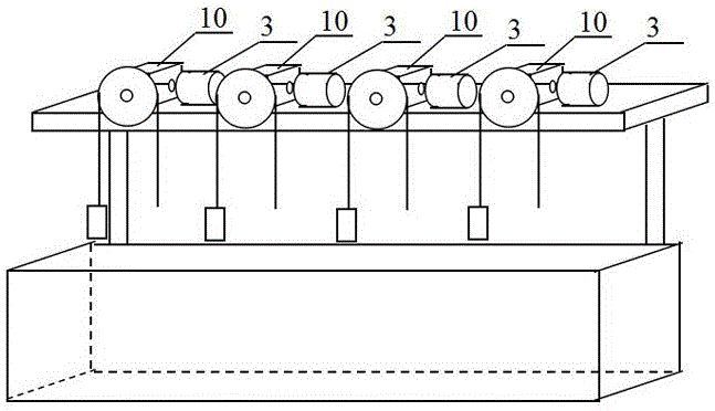
[0016] Such as figure 2 Shown: a quenching robot, including a quenching tank 1 for storing quenching medium and four lifting mechanisms for driving the quenched workpiece 9 to lift, the upper end of the quenching tank 1 is open, and the quenching tank 1 is also set There are an inlet pipe 6 and an outlet pipe 8, the outlet pipe 8 is located below the inlet pipe 6, and a pipeline booster pump 7 for pressurizing the quenching medium is arranged between the outlet pipe 8 and the inlet pipe 6, and the lifting mechanism passes through the bracket 2 Set on one side of the quenching tank 1, the lifting mechanism includes a motor 3, a sprocket 4 connected to the output end of the motor 3 and a chain 5 matching with the sprocket 4, and a reducer is arranged between the sprocket 4 and the output shaft of the motor 3 10. One end of the chain 5 is the connection end of the workpiece to be quenched, and the other end of the chain 5 is the free end.

[0017] The quenching robot of the pre...


PUM


Abstract

The invention relates to a quenching robot. The quenching robot comprises a quenching tank and a lifting mechanism. The upper end of the quenching tank is opened, and the quenching tank is further provided with an inlet pipe and an outlet pipe. The outlet pipe is located below the inlet pipe. A pipeline pressurizing pump for pressurizing quenching media is arranged between the outlet pipe and the inlet pipe. The lifting mechanism comprises a motor, a chain wheel and a chain. One end of the chain is a quenched workpiece connecting end, and the other end of the chain is a free end. According to the quenching robot, the motor is used for driving a quenched workpiece to move up and down, so that the quenched workpiece is subjected to alternated cooling in air and liquid media, manual quenching operation is replaced, the labor intensity of quenching workers is relieved, the quenching quality can be stabilized as well, and the ideal quenching effect is achieved. Through control over the rotation direction, the rotation speed, the staying time and the like of the motor, the staying time, namely the cooling time, of the quenched workpiece in the air and the quenching media is controlled, and accordingly the purpose of changing the cooling speed is achieved.

Description

technical field [0001] The invention relates to the technical field of heat treatment, in particular to a quenching robot. Background technique [0002] Quenching is the most important process in heat treatment. In this process, the workpiece is heated and kept warm, and then cooled to obtain lower bainite, martensite or their mixed structure; cooling is the most critical process in the quenching process. Cooling If the speed is slow, martensite cannot be obtained, and the purpose of quenching cannot be achieved. If the cooling speed is fast, it will easily cause deformation and cracking of the workpiece, and the workpiece will be scrapped. In order to prevent deformation and cracking of the workpiece, the cooling rate of the workpiece should be slowed down as much as possible. The ideal cooling rate is: at the ferrite transformation temperature Ar 3 Or pearlite start transition temperature Ar 1 Above, the cooling rate can be very slow, in Ar 3 or Ar 1 The cooling rate ...

Claims


Application Information

Patent Timeline
Patent Type & Authority Applications(China)
IPC IPC(8): C21D1/63C21D9/00
CPCC21D1/63C21D9/0062
Inventor 杨玉丹田东伟刘奇奇刘顺常宝林王顺兴
Owner HENAN UNIV OF SCI & TECH
Why Eureka
Try Eureka