Engineering vehicle temperature control system and method based on double-cooling loop split radiator

A technology for engineering vehicles and temperature control systems. It is applied in the control of coolant flow, liquid cooling, and engine cooling. It can solve the uneven distribution of air volume on the surface of the radiator, the inability to meet the rapid temperature rise of the engine, and the uncontrollable speed of the cooling fan. problems, to avoid insufficient cooling capacity or excessive cooling problems, shorten the warm-up time, and reduce the effect of pressure drop

Active Publication Date: 2017-05-24
JILIN UNIV
View PDF14 Cites 13 Cited by
  • Summary
  • Abstract
  • Description
  • Claims
  • Application Information

AI Technical Summary

Problems solved by technology

The traditional engineering vehicle cooling system mostly adopts the arrangement of mechanically driven cooling fans and radiator groups in front and back. This arrangement is likely to cause the cooling air to interfere with each other among the radiators, making the air volume distribution on the surface of some radiators uneven, resulting in transmission Decreased thermal coefficient Decreased cooling capacity
The pressure loss of the ...

Method used


Image

  • Engineering vehicle temperature control system and method based on double-cooling loop split radiator
  • Engineering vehicle temperature control system and method based on double-cooling loop split radiator

Examples


Embodiment Construction

[0019] The detailed content of the present invention and its specific implementation will be further described below in conjunction with the accompanying drawings.

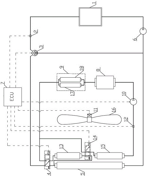
[0020] see figure 1As shown, the engineering vehicle temperature control system based on the dual cooling circuit split radiator of the present invention includes a high temperature cooling circuit, a low temperature cooling circuit, an engine 1, a heat collecting device 9, an intercooler 8, a high temperature radiator 5, a low temperature heat dissipation 15, auxiliary radiator 13, high temperature circuit water pump 6, low temperature circuit electric control water pump 10, electronic thermostat 3, fan 16, motor 11, first electromagnetic reversing valve 4, second electromagnetic reversing valve 14, ECU7, When the high-temperature circuit temperature sensor 2, the low-temperature circuit temperature sensor 12, and the electronic thermostat 3 are not turned on, the engine 1 coolant returns to the engine 1 through ...


PUM


Abstract

The invention relates to an engineering vehicle temperature control system and method based on a double-cooling loop split radiator, and belongs to the field of engineering vehicle intelligent temperature control. The engineering vehicle temperature control system has the beneficial effects that a high-temperature cooling loop and a low temperature cooling loop are designed according to characteristics of a system heat source, in the low-temperature cooling loop, cooling liquids of a transmission oil heat exchanger and a hydraulic oil heat exchanger which are arranged in a parallel manner do not interfere with each other, and the problem of insufficient cooling capacity or overcooling is avoided; a water cooling type intercooler, the hydraulic oil heat exchanger and the transmission oil heat exchanger with smaller size are adopted, so that the total weight of a radiator module is decreased while the heat exchange efficiency is improved, the manufacturing cost is reduced, arrangement is more convenient in a limited engine compartment space, and pressure loss of air when flowing through the radiator module is reduced; and through controlling the working state of an electromagnetic reversing valve, an ECU achieves the function of automatically matching the radiator according to the heat dissipation requirements of heat sources in the high-temperature cooling loop and the low temperature cooling loop, the utilization efficiency of the radiator is improved, and the purpose of reducing power consumption of the system is achieved.

Description

technical field [0001] The invention relates to the technical field of intelligent temperature control of engineering vehicles, in particular to an engineering vehicle temperature control system and method based on a dual cooling circuit split radiator. Background technique [0002] The main function of the engineering vehicle temperature control system is to ensure that the corresponding systems of the engineering vehicle (engine system, intake booster system, transmission system and hydraulic system) always work within a suitable temperature range. The operating environment of engineering vehicles is relatively harsh. Due to the limited space in the power cabin, there are often multiple heat sources and radiators that interfere with each other in the power cabin. Hidden danger. Excessively high or low working temperature of each system of engineering vehicles will cause damage to the vehicle, so the problem of vehicle thermal management has always been the focus of resear...

Claims


Application Information

Patent Timeline
IPC IPC(8): F01P3/20F01P3/18F01P7/16F01P7/04F01P7/08F01P11/16
CPCF01P3/18F01P3/20F01P7/048F01P7/08F01P7/164F01P7/165F01P11/16F01P2003/182F01P2060/02Y02T10/12
Inventor 刘扬王帅孙超秦四成薛耀
Owner JILIN UNIV
Why Eureka
Try Eureka