
A device and method for detecting longitudinal cracks in pipelines based on fiber grating sensing

A fiber grating and longitudinal crack technology, applied in the direction of measuring devices, optical devices, pipeline systems, etc., can solve problems such as troublesome installation, inability to accurately measure the specific position of pipeline cracks, difficulty in moving and reusing, etc., to reduce The effect of cost detection, accurate positioning, and work efficiency improvement

Active Publication Date: 2019-04-30
WUHAN UNIV OF TECH
View PDF8 Cites 0 Cited by
  • Summary
  • Abstract
  • Description
  • Claims
  • Application Information

AI Technical Summary

Problems solved by technology

[0003] The premise of monitoring a cracked pipeline is to detect the pipeline to determine the location of the crack. At present, the commonly used pipeline detection methods include ultrasonic detection, magnetic leakage detection and fiber Bragg grating sensor detection. Fiber Bragg grating sensor detection is compared with ultrasonic detection and magnetic leakage detection. , has many advantages such as compactness, lightness, good stability, acid and alkali resistance, anti-electromagnetic interference, high precision, no spark, strong multiplexing ability, and easy realization of long-distance multi-channel telemetry and control. However, the existing fiber grating The sensor detection has the following problems: 1) The existing fiber grating sensor detection is generally used to detect leaks, there is no detection design for cracks, and the specific location of the pipeline crack cannot be accurately measured; 2) the fiber grating sensor is generally installed by sticking, the installation cumbersome, difficult to move and reuse

Method used


Image

  • A device and method for detecting longitudinal cracks in pipelines based on fiber grating sensing
  • A device and method for detecting longitudinal cracks in pipelines based on fiber grating sensing
  • A device and method for detecting longitudinal cracks in pipelines based on fiber grating sensing

Examples


Embodiment Construction

[0020] The present invention will be further described below in conjunction with the accompanying drawings and embodiments.

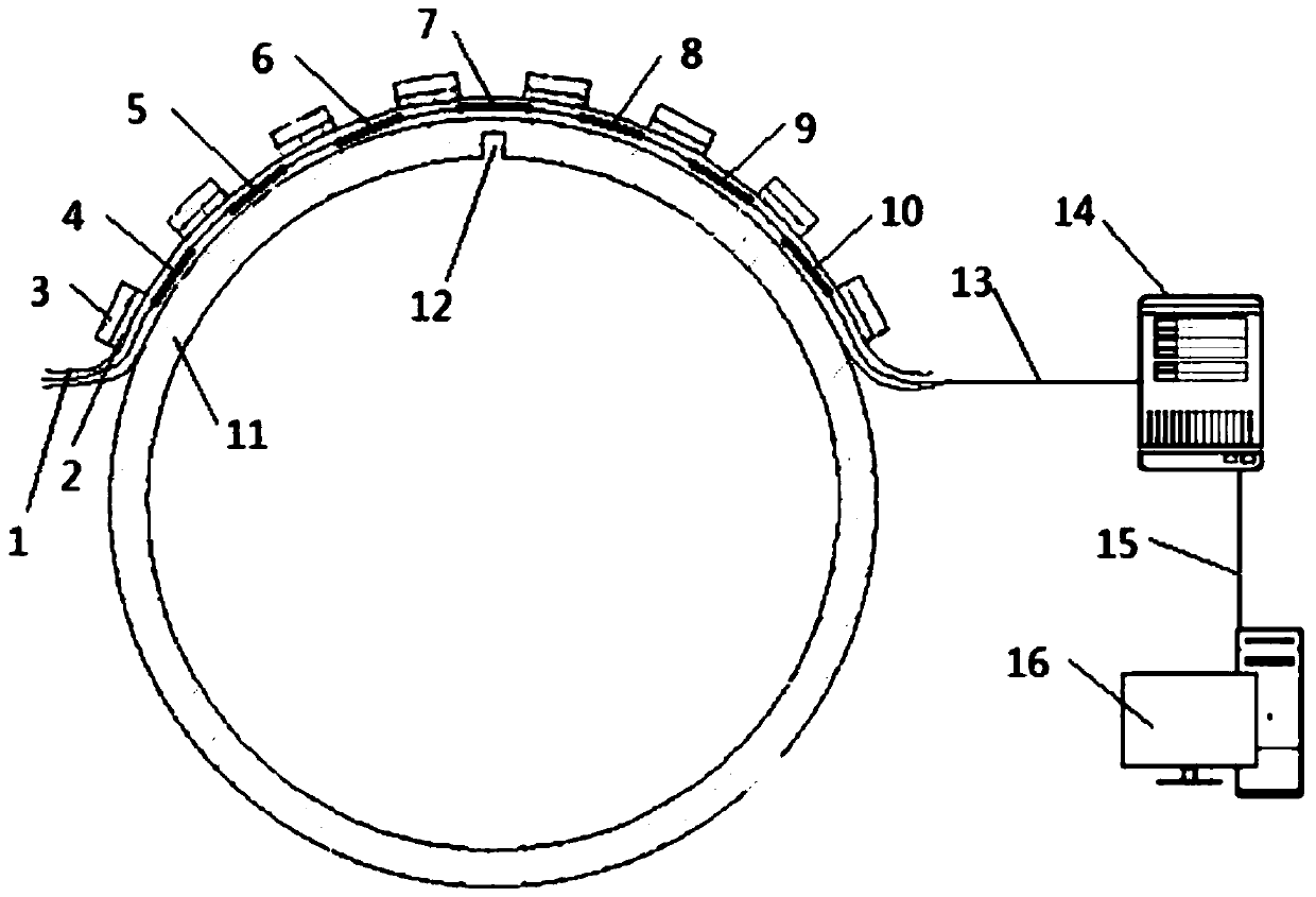
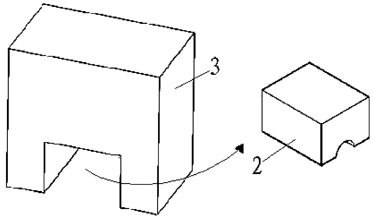
[0021] Such as figure 1 As shown, a pipeline longitudinal crack detection device based on fiber Bragg grating sensing includes a fiber grating array sensor, a fiber grating demodulator 14 and a data processing system 16 connected in sequence. The fiber grating array sensor is arranged along the outer wall of the pipeline 11 circumferentially, The fiber grating array sensor comprises a packaged optical fiber 1 and fiber gratings equidistantly distributed on the optical fiber 1 (in this embodiment, 7 fiber gratings are set, and the specific number can be selected according to the actual situation, not only 7 fiber gratings can be used. 1), the fiber grating array sensor is clamped and fixed on the outer wall of the pipeline 11 by the magnet 3 after being pre-stretched. The magnet 3 is located at the interval between adjacent fiber gratings and outside th...


PUM


Abstract

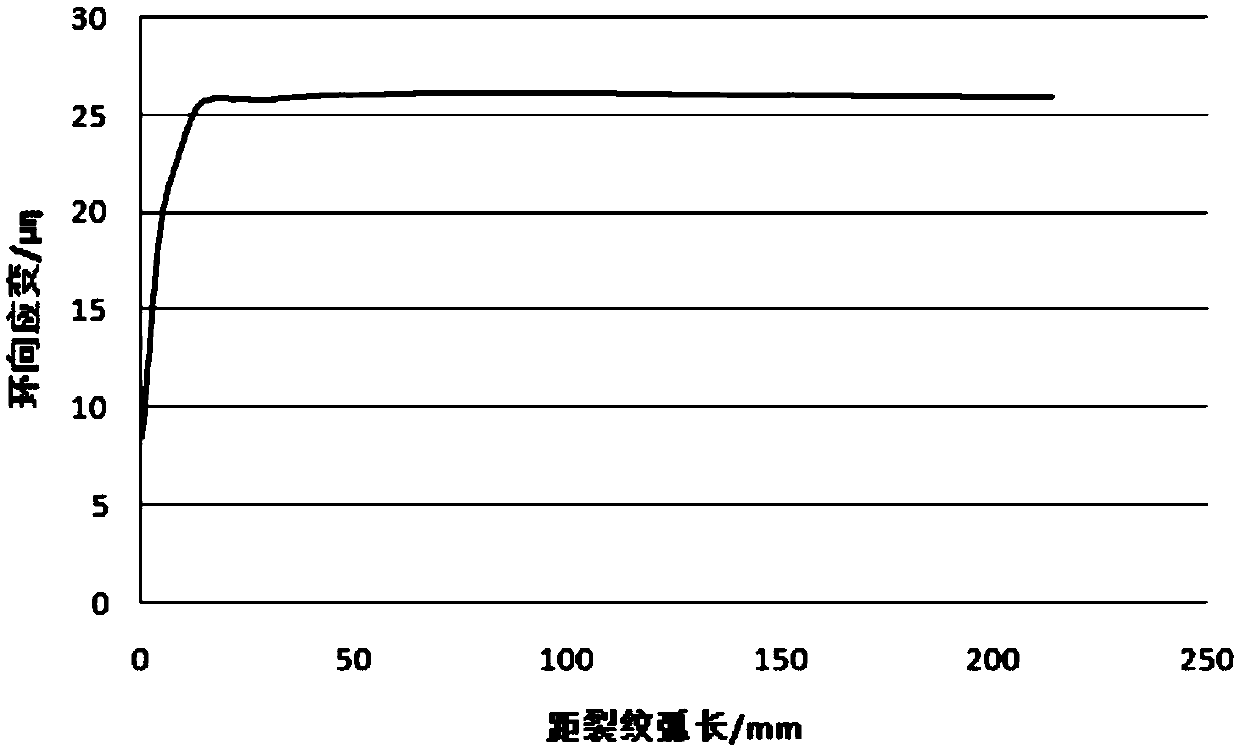
The invention relates to a pipeline longitudinal crack detection device and method based on fiber grating sensing. A fiber grating array sensor is arranged on the periphery of an outer wall of a pipeline, and comprises an optical fiber and fiber gratings equally distributed on the optical fiber; the fiber grating array sensor is pre-stretched so as to be clamped and fixed on the outer wall of the pipeline through a magnet, and demodulates a local hoop strain measured by each fiber grating so as to transmit to a data processing unit; the hoop strains of a pipeline with a longitudinal crack are symmetrically distributed by adopting the crack as a center; the local hoop strain at the crack part is the smallest; in a section of area close to the crack, the local hoop strains are increased along the increase of the distance away from the crack; in a section of area far away from the crack, the local hoop strains approach to a constant number; the data processing unit finds out the smallest local hoop strain according to the changing situation of the hoop strains so as to determine a position of the longitudinal crack of the pipeline. According to the pipeline longitudinal crack detection device and the method based on fiber grating sensing provided by the invention, the accurate positioning of the crack is realized, and the fiber grating array sensor is convenient to disassemble and utilize.

Description

technical field [0001] The invention belongs to the technical field of pipeline detection, and in particular relates to a pipeline longitudinal crack detection device and method based on fiber grating sensing. Background technique [0002] Pipelines are widely used in chemical industry, electric power, metallurgy, transportation and other industries. When the pipeline is exposed to high temperature and high pressure corrosion environment for a long time, it is easy to generate cracks during service. Some cracks have no effect on the use of pipelines. In this case, cracks It is uneconomical to deal with, but some cracks are often the main cause of medium leakage in pipelines and explosions caused by medium leakage. Therefore, monitoring cracked pipelines and conducting safety assessments based on the monitored data can not only ensure the long-term safety of pipelines It can also avoid uneconomical behaviors such as replacement or repair. [0003] The premise of monitoring a...

Claims


Application Information

Patent Timeline
Patent Type & Authority Patents(China)
IPC IPC(8): G01B11/00G01B11/16F17D5/00
CPCF17D5/00G01B11/00G01B11/165G01B11/18
Inventor 梁磊王慧许儒泉冯坤徐刚张健吴慧峰李东旭曹珊仇磊涂彬段细云蔡彦璞王仁亮罗玉文王永皎夏竹清
Owner WUHAN UNIV OF TECH
Learn More