
Capillary liquid chromatographic column temperature control device

A technology of a liquid chromatography column and a temperature control device is applied in the field of a capillary liquid chromatography column temperature control device, and can solve the problems that the mobile phase cannot fully achieve temperature equilibrium, the column temperature box cannot be well used, and the separation reproducibility is affected. , to achieve the effect of uniform heating, precise control of operating temperature and solving heating problems

Inactive Publication Date: 2017-05-24
厦门宜柱科技有限公司
View PDF8 Cites 5 Cited by
  • Summary
  • Abstract
  • Description
  • Claims
  • Application Information

AI Technical Summary

Problems solved by technology

[0004] Most of the traditional chromatographic column ovens can only support capillary columns with a length of about 15cm. For complex samples of biological macromolecules such as proteins and peptides, the column length needs to reach 50cm or even longer to obtain satisfactory results in a single run. Satisfactory resolving power, which makes traditional column thermostats not suitable for research fields such as proteomics
At the same time, the heating range of the traditional column thermostat is short, and the mobile phase cannot fully achieve temperature equilibrium in the column tube, which affects the separation reproducibility. These shortcomings restrict the function of the traditional column thermostat in actual use.

Method used


Image

  • Capillary liquid chromatographic column temperature control device

Examples


Embodiment Construction

[0019] The following embodiments will further illustrate the present invention in conjunction with the accompanying drawings.

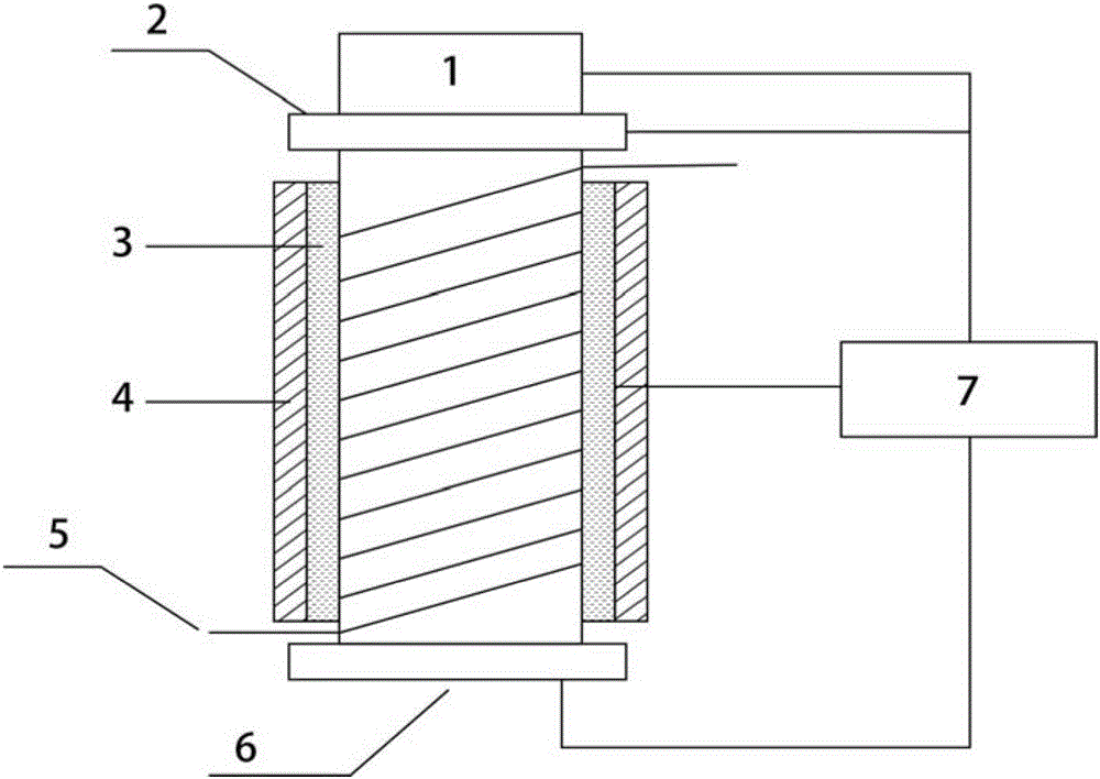
[0020] see figure 1 The embodiment of the present invention is provided with a cooling fan 1, a hollow capillary column support tube 2, a capillary liquid chromatography column 5, a temperature control device 7 and a base 6, and the cooling fan 1 is installed on the top of the hollow capillary column support tube 2. The outer periphery of the hollow capillary column support cylinder 2 is coated with an electric heating coating, and the hollow capillary column support cylinder 2 is engraved with thread grooves, and the thread grooves are used to fix the capillary liquid chromatography column 5, and the capillary liquid chromatography The column 5 is spirally wound on the surface of the hollow capillary column support tube 2; the outer periphery of the hollow capillary column support tube 2 wrapped with the capillary liquid chromatography column 5 is co...


PUM

PropertyMeasurementUnit
thicknessaaaaaaaaaa
thicknessaaaaaaaaaa
thicknessaaaaaaaaaa

Abstract

The invention relates to a capillary liquid chromatographic column temperature control device, and relates to a capillary liquid chromatographic column. The capillary liquid chromatographic column temperature control device comprises a cooling fan, a hollow capillary column supporting tube, a capillary liquid chromatographic column, a temperature control device and a base, wherein the cooling fan is arranged at the top of the hollow capillary column supporting tube, and the periphery of the hollow capillary column supporting tube is covered with an electric heating coating layer; a threaded groove is engraved in the outside of the hollow capillary column supporting tube and is used for fixing the capillary liquid chromatographic column, and the capillary liquid chromatographic column is spirally wound on the surface of the hollow capillary column supporting tube; the periphery of the hollow capillary column supporting tube wound with the capillary liquid chromatographic column is covered with a temperature sensitive resistance layer, and the temperature control device is provided with a temperature sensor and a display device; the temperature sensor is used for detecting the temperature of the temperature sensitive resistance layer, and the temperature signal output terminal of the temperature sensor is connected with the display device; and the temperature signals of the temperature sensor are displayed by the display device, and the hollow capillary column supporting tube is arranged on the base.

Description

technical field [0001] The invention relates to a capillary liquid chromatography column, in particular to a capillary liquid chromatography column temperature control device. Background technique [0002] Since the 1980s, with the development of chromatographic theory and related technologies, people have gradually realized the advantages of micro-separation systems. Small, can greatly improve the detection sensitivity, so it is more suitable for the analysis and detection of trace samples. At the same time, due to the reduced flow rate, the amount of organic solvent required per unit operating time is reduced, thereby limiting the consumption of toxic solvents and saving operating costs. In addition, when using liquid chromatography-mass spectrometry online tandem analysis technology, the lower flow rate can improve the atomization efficiency of the electrospray ion source and further improve the detection sensitivity of mass spectrometry, which is suitable for qualitativ...

Claims


Application Information

Patent Timeline
Patent Type & Authority Applications(China)
IPC IPC(8): G01N30/30
CPCG01N30/30
Inventor 张博周拙恒
Owner 厦门宜柱科技有限公司
Learn More