Precisely-controllable gas supply system

An air supply system, precise technology, applied in control/regulation system, non-electric variable control, simultaneous control of multiple variables, etc., can solve the problem of inability to provide accurately controllable temperature, humidity and flow gas, and achieve the gas path structure Simple, precise control effects

Inactive Publication Date: 2017-05-24
无锡帕捷科技有限公司
View PDF5 Cites 14 Cited by
  • Summary
  • Abstract
  • Description
  • Claims
  • Application Information

AI Technical Summary

Problems solved by technology

[0003] Aiming at the shortcomings that the existing gas control system cannot provide accurate and controllable temperature, humidity and flow gas, the applicant designed an accurate and controllable gas supply system with a reasonable gas path structure, which can accurately control the temperature, humidity and flow rate of the gas at the same time

Method used


Image

  • Precisely-controllable gas supply system
  • Precisely-controllable gas supply system

Examples


Embodiment 1

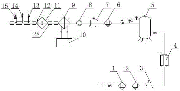
[0025] Such as figure 1 As shown, the precise and controllable air supply system of the present invention includes a drying module, a flow control module, a temperature control module, and a detection module connected in series in sequence. The inlet end of the coarse-efficiency filter 1 of the drying module is connected to an external air source, and the outlet end is connected to the fine-efficiency filter 2, and then connected to the athermal adsorption dryer 4 through a manual pressure reducing valve 3, and the dried gas enters Gas storage tank 5. The gas outlet end of the gas storage tank 5 is connected to the mass flow controller 8 through the precision filter 6 and the electric proportional valve 7 of the flow control module. The air outlet of the mass flow controller 8 is connected to the refrigeration evaporator 9 and the heater 11 of the temperature control module in sequence. The refrigeration evaporator 9 is also connected to the refrigeration system 10, and an over...

Embodiment 2

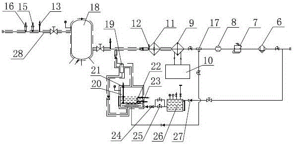
[0028] Such as figure 2 As shown, the precise and controllable gas supply system of the present invention uses the three-way split valve 17 after the flow control module to divide the gas into two paths after passing through the temperature control module and the humidity control module respectively, and then merge into one gas and flow through the detection module. , The output flow, temperature and humidity are all precisely controllable gas. The drying module in this embodiment is the same as the drying module in the first embodiment. It consists of a coarse-effect filter 1, a fine-effect filter 2, a manual pressure reducing valve 3, a thermal adsorption dryer 4, and a gas storage tank in series. 5 composition (not shown in the figure). The outlet end of the air storage tank 5 is connected to a flow control module all the way, including a precision filter 6, an electric proportional valve 7 and a mass flow controller 8 connected in sequence; the other way is connected to t...


PUM


Abstract

The invention discloses a precisely-controllable gas supply system, which comprises a drying module, a flow control module, a temperature control module and a detection module which are connected in series, wherein a refrigeration evaporator and a heater of the temperature control module are installed on a same pipeline, gas subjected to drying processing flows through the refrigeration evaporator and the heater sequentially after the flow of the gas is controlled by means of a quality flow controller, thus the gas with controllable temperature and flow is obtained, and the gas circuit is simple in structure and precise in control. The precisely-controllable gas supply system further comprises a humidity control module on the basis of the controllable temperature and flow, a gas outlet end pipeline of the quality flow controller is provided with a three-way diverging valve, a certain flow of dry gas controlled by the quality flow controller is divided into two paths by means of the three-way diverging valve, one path undergoes temperature control by means of the temperature control module, the other path undergoes humidification by means of a humidifying barrel of a humidifying module and a drain valve, and the gas with precisely-controllable temperature, humidity and flow is obtained after mixing the two paths of gases.

Description

Technical field [0001] The invention relates to the field of testing equipment, in particular to a precise and controllable gas supply system that provides temperature controllable, humidity controllable and flow controllable. Background technique [0002] Some existing high and low temperature tests or corrosion resistance tests need to be carried out under the conditions of precise control of temperature, humidity and flow. Therefore, the test gas supply system needs to provide gas with controllable temperature, humidity and flow. However, the current air supply system usually sets two parallel hot and cold air lines to control the temperature. The heating or cooling lines are opened according to the target temperature. However, because the air source temperature is unstable, the control system may need to switch the heating or cooling lines. The circuit work, the gas circuit and the control system are complicated, and the gas temperature fluctuates unstable during the switchin...

Claims


Application Information

Patent Timeline
Patent Type & Authority Applications(China)
IPC IPC(8): G05D27/02
CPCG05D27/02
Inventor 范洪峰马龙进
Owner 无锡帕捷科技有限公司
Why Eureka
Try Eureka