Power battery air heat management system for pure electric vehicle and operating method of system

A battery management system, a technology for pure electric vehicles, applied in electric vehicles, electric traction, electrical components, etc., can solve the problems of inability to meet the thermal management of power batteries, increase extra battery power consumption, and inability to cool batteries, etc. Low power consumption and the effect of recycling

Active Publication Date: 2017-05-24
SHANDONG UNIV OF SCI & TECH
View PDF9 Cites 8 Cited by
  • Summary
  • Abstract
  • Description
  • Claims
  • Application Information

AI Technical Summary

Problems solved by technology

[0004] Most of the air cooling solutions currently used are relatively simple, and some of them expose the battery to the air for natural cooling, which cannot meet the needs of power battery thermal management
The cooling scheme of some power batteries adopts constant forced cooling, which cannot be cooled according to the temperature change of the battery, which increases the extra consumption of battery power and has poor energy saving effect

Method used


Image

  • Power battery air heat management system for pure electric vehicle and operating method of system
  • Power battery air heat management system for pure electric vehicle and operating method of system
  • Power battery air heat management system for pure electric vehicle and operating method of system

Examples


Embodiment 1

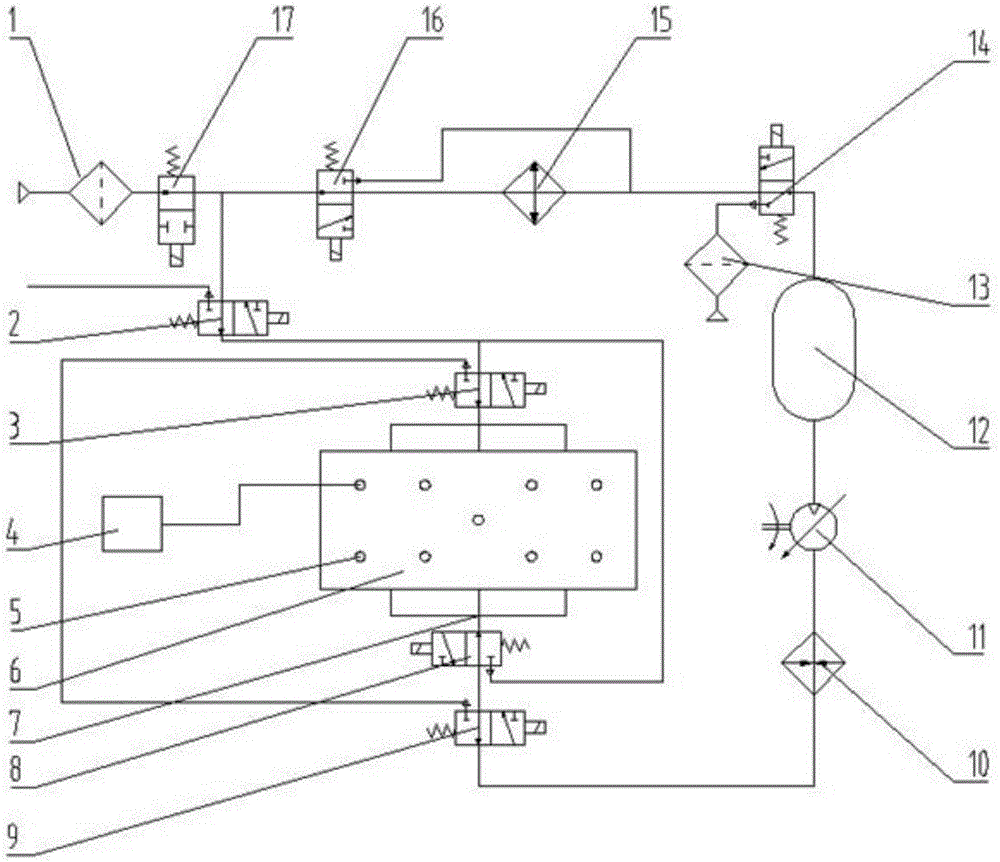
[0044] An air heat management system for a power battery of a pure electric vehicle, comprising an air distribution pipeline 7 connected to a power battery pack box 6, a temperature sensor 5 and a battery management system integrated machine 4;

[0045] One end of the air distribution pipeline 7 is sequentially connected to the heater 10, the air pump 11, the air storage tank 12, the two-position three-way electromagnetic reversing valve E14, the cooler 15, the two-position three-way electromagnetic reversing valve F16 and the two-position two-way electromagnetic reversing valve The reversing valve 17, wherein the two-position three-way electromagnetic reversing valve E14 is also connected to the two-position three-way electromagnetic reversing valve F16 through the pipeline; the other end of the air distribution pipeline 7 is connected to the two-position three-way electromagnetic reversing valve A2 and the two-position three-way electromagnetic reversing valve A2 Two-way elec...

Embodiment 2

[0053] An air heat management system for a pure electric vehicle power battery, the structure of which is as described in Example 1, the difference is that the air heat management system also includes a two-position three-way electromagnetic reversing valve B3, a two-position three-way electromagnetic reversing valve C8 and the two-position three-way electromagnetic reversing valve D9, one end of the air distribution pipeline 7 is connected to the heater 10 after connecting the two-position three-way electromagnetic reversing valve C8 and the two-position three-way electromagnetic reversing valve D9; the air distribution pipeline 7 The other end is connected to the two-position three-way electromagnetic reversing valve B3 and then connected to the two-position three-way electromagnetic reversing valve A2, and the two-position three-way electromagnetic reversing valve C7 is also connected to the two-position three-way electromagnetic reversing valve through the pipeline Valve A2...

Embodiment 3

[0056] A working method of an air heat management system for a power battery of a pure electric vehicle, using the air heat management system described in Embodiment 2, the specific working process includes the following steps,

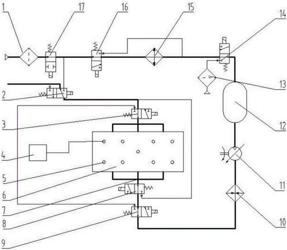
[0057] A gas storage circulation mode: (such as figure 2 shown)

[0058] When the pure electric vehicle starts to start, the all-in-one battery management system 4 starts the air storage circulation mode, at this time, the two-position three-way electromagnetic reversing valve A2 is energized, and the air pump 11 is started to perform air circulation;

[0059] In this mode, the toxic gas released by the battery in the whole system is discharged, and at the same time, it is tested whether the whole system is unobstructed, so as to prevent the system from being blocked due to long-term failure of the air filter element or internal structural failure, and to ensure that there is enough air in the air storage tank. Air, ready for internal circulation of...


PUM


Abstract

The invention relates to a power battery air heat management system for a pure electric vehicle and an operating method of the system. The power battery air heat management system for the pure electric vehicle comprises an air distribution pipeline connected with a power battery pack box, a temperature sensor and a battery management system all-in-one machine, wherein one end of the air distribution pipeline is sequentially connected with a heater, an air pump, an air storage tank, a two-position three-way electromagnetic directional valve E, a cooler, a two-position three-way electromagnetic directional valve F and a two-position two-way electromagnetic directional valve; the two-position three-way electromagnetic directional valve E is connected with the two-position three-way electromagnetic directional valve F through a pipeline; and the other end of the air distribution pipeline is sequentially connected with a two-position three-way electromagnetic directional valve A and the two-position two-way electromagnetic directional valve. The power battery air heat management system disclosed by the invention has multiple temperature regulation modes, is capable of performing corresponding mode selection aiming at different battery conditions, realizing reasonable and fine management of the power battery and realizing automatic switch and control of multiple modes according to the temperature change in the battery box, and has the advantages of accurate adjustment, rapid switch and the like.

Description

technical field [0001] The invention relates to a pure electric vehicle power battery air heat management system and a working method thereof, belonging to the technical field of electric vehicles. Background technique [0002] With the rapid development of the economy, the global energy shortage and environmental pollution are becoming more and more serious. The development of pure electric vehicles has become an effective way to solve this problem. As the core component that restricts the development of electric vehicles, power batteries have always been a hot spot that many R&D and production units are rushing to invest in. Among them, thermal management of power battery has become one of the key technologies. [0003] The current battery thermal management methods for engineering applications mainly include air cooling and liquid cooling. The structure of the liquid cooling system is complex, the mass is large, it is easy to short circuit, and the cooling medium is eas...

Claims


Application Information

Patent Timeline
Patent Type & Authority Applications(China)
IPC IPC(8): H01M10/613H01M10/625H01M10/6561H01M10/6566H01M10/635H01M10/633H01M10/42B60L11/18
CPCH01M10/425H01M10/613H01M10/625H01M10/633H01M10/635H01M10/6561H01M10/6566B60L58/26H01M2010/4271Y02T10/70Y02E60/10
Inventor 张鑫王通赵森庆曾庆良李旭杨延超徐海港王志文姜考
Owner SHANDONG UNIV OF SCI & TECH
Why Eureka
Try Eureka