
Motor drive fault-tolerant control device and electric device

A fault-tolerant control, electric drive technology, applied in the direction of AC motor control, control system, electrical components, etc., can solve the problem of inability to apply and popularize, increase cost, difficulty and complexity, restrict high-power motors, electric drives and electric components. Equipment electric military equipment development and other issues, to avoid sudden changes in performance indicators, improve reliability and safety

Pending Publication Date: 2017-05-24
UNIV OF SHANGHAI FOR SCI & TECH
View PDF0 Cites 14 Cited by
  • Summary
  • Abstract
  • Description
  • Claims
  • Application Information

AI Technical Summary

Problems solved by technology

However, the design, manufacture and control methods of high-phase motors are different from traditional design, manufacture and control methods, which not only increases the cost, difficulty and complexity of production, but also cannot be carried out when the relevant technology is not yet mature. Application and popularization restrict the development of high-power motors, electric drives and electric equipment, especially electric military equipment

Method used


Image

  • Motor drive fault-tolerant control device and electric device
  • Motor drive fault-tolerant control device and electric device

Examples


Embodiment Construction

[0025] The specific implementation manners of the present invention will be described below in conjunction with the accompanying drawings.

[0026] The electric drive fault-tolerant control device 10 is set in electric equipment such as electric tools, quadcopters, electric vehicles, electric ships, electric forklifts, and electric military equipment, and is used to drive electric equipment.

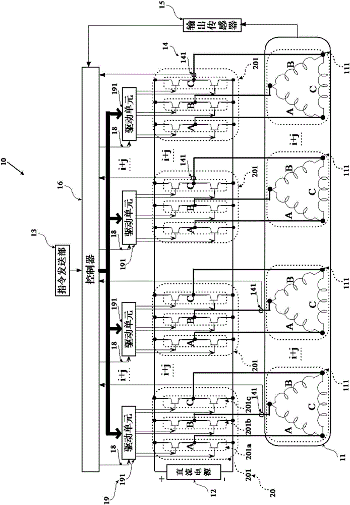
[0027] figure 1 It is a schematic diagram of the circuit structure of the electric drive fault-tolerant control device in this embodiment.

[0028] Such as figure 1 As shown, the electric drive fault-tolerant control device 10 includes a multi-phase motor 11 , a DC power supply 12 , a command sending unit 13 , a current sensor 14 , an output sensor 15 , a controller 16 , a driver 19 and a power converter 20 .

[0029] The multi-phase motor 11 has k phases and has a rated line voltage and a rated line current. The multi-phase motor 11 is any one of an asynchronous motor, a synchronou...


PUM


Abstract

The present invention provides a motor drive fault-tolerant control device and an electric device. The device comprises a polyphase machine, a direct current source, an instruction sending part, a current sensor, an output sensor, a controller, a driver and a power converter. The polyphase machine winding has (k-1)(i+j) mutually independent polyphase winding units with the same parameters, the power converter has power conversion units correspondingly connected with the polyphase winding units, each polyphase winding unit has k power conversion circuits configured to provide k-way line current to the corresponding polyphase winding units, the driver has (k-1)(i+j) driving units which are respectively connected with power conversion units, the current sensor has current detection units correspondingly connected with the power conversion units, the number of the current detection units configured to detect each phase outputted line current is equal to (i+j), k is a positive integer of larger than 2, j is a positive integer of larger than 1, and i is a redundant number and a natural number.

Description

technical field [0001] The invention belongs to the field of motors, in particular to an electric drive fault-tolerant control device with fault-tolerant function and electric equipment. Background technique [0002] In today's society, the requirements for environmental protection are getting higher and higher, and the environmental protection standards of various equipment are also increasing. In order to better protect the environment, the state has issued various policies and vigorously promoted new energy and renewable energy. [0003] At present, using electric energy as the driving force of various equipment has become the mainstream of equipment development. Electric equipment such as electric vehicles and electric forklifts that use electricity as energy are increasingly favored by manufacturers and consumers. Electric equipment not only has less pollution and can provide electric energy through renewable energy, but also has the advantages of high energy utilizat...

Claims


Application Information

Patent Timeline
IPC IPC(8): H02P25/22H02P23/00
CPCH02P23/00H02P25/22
Inventor 金爱娟李少龙
Owner UNIV OF SHANGHAI FOR SCI & TECH
Learn More