Supercharge Your Innovation With Domain-Expert AI Agents!

Machining platform for SMT laser template spraying device

A technology of spraying equipment and processing platform, applied in the direction of spraying device, etc., can solve the problems of nano-solution entering and adsorption device failure, etc., and achieve the effect of avoiding failure, convenient operation and high practicability

Inactive Publication Date: 2017-05-31
绍兴柯桥茂良化纤有限公司
View PDF6 Cites 4 Cited by
  • Summary
  • Abstract
  • Description
  • Claims
  • Application Information

AI Technical Summary

Problems solved by technology

[0007] For this reason, the technical problem to be solved by the present invention is that the processing platform of the nano-solution spraying equipment used for SMT laser templates in the prior art is easy to cause the nano-solution to enter the vacuum adsorption hole on the vacuum adsorption disk, thereby affecting the failure of the adsorption device. , so as to propose a processing platform for SMT laser template spraying equipment

Method used


Image

  • Machining platform for SMT laser template spraying device
  • Machining platform for SMT laser template spraying device
  • Machining platform for SMT laser template spraying device

Examples


Embodiment Construction

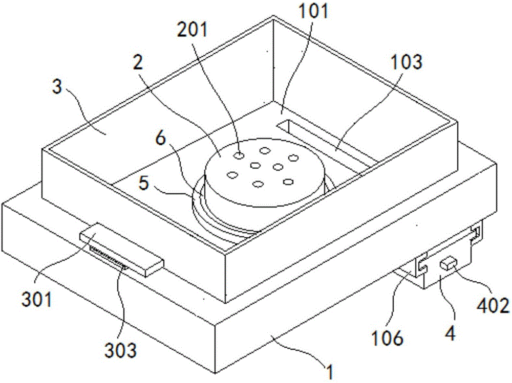
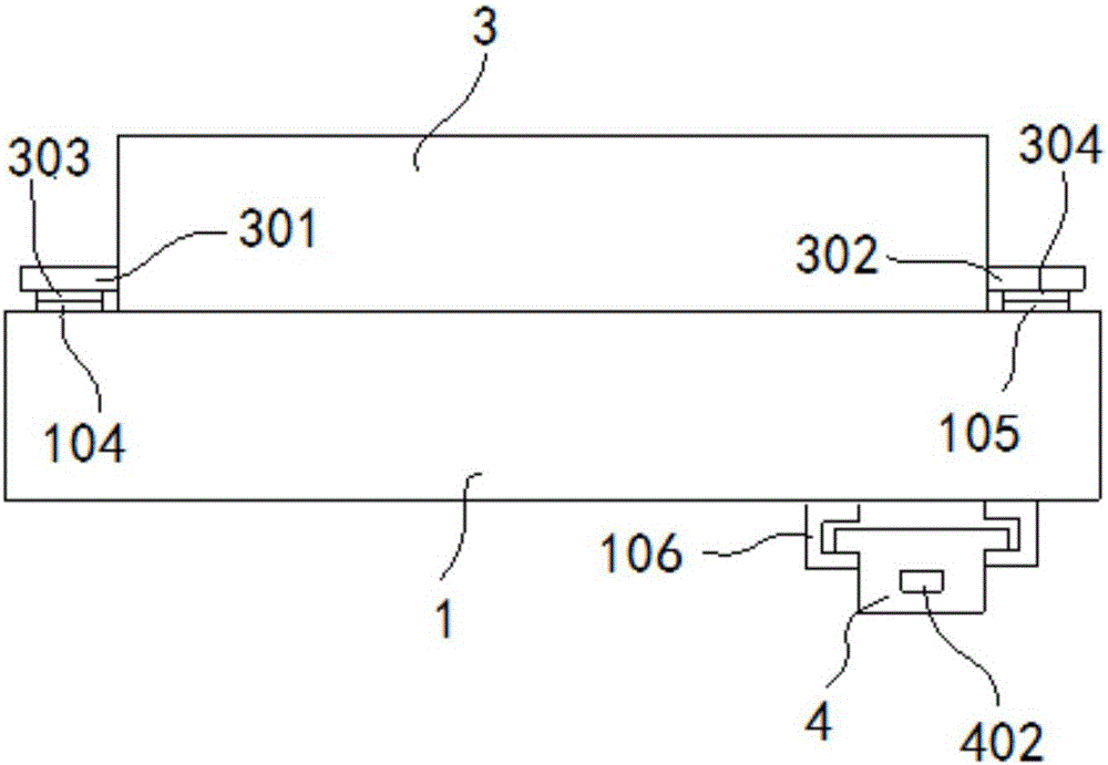
[0029] Such as figure 1 , figure 2 As shown, the processing platform for SMT laser template spraying equipment of the present invention includes:

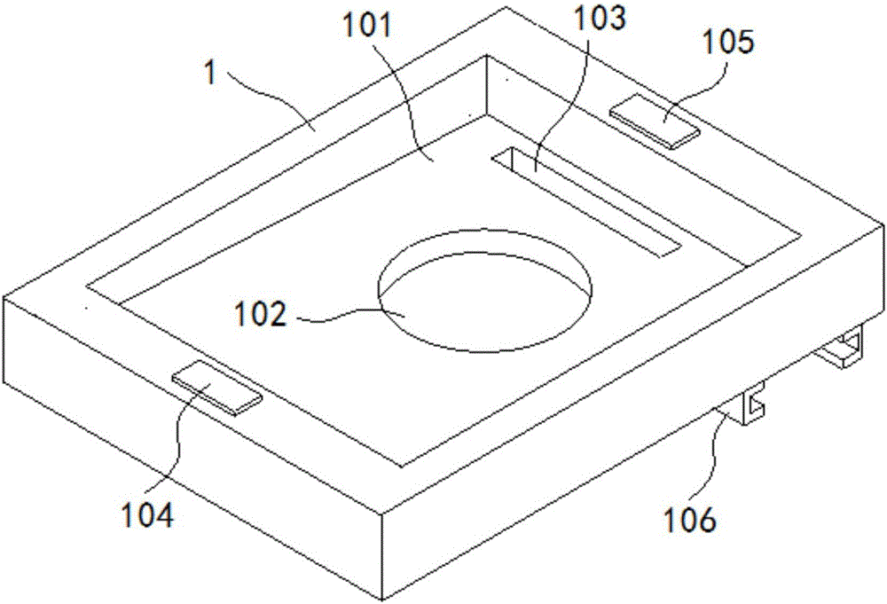
[0030] Backplane 1, such as image 3 As shown, a rectangular concave platform 101 is formed on the base plate 1, the upper surface of the concave platform 101 is inclined from left to right, and a through hole 102 is formed at the center of the concave platform 101. The concave platform 101 The right side of the base plate 1 is formed with a drain tank 103, and the upper surface of the bottom plate 1 is fixedly connected with a first magnet chuck 104 and a second magnet chuck 105 which are oppositely arranged. A slot 106 is formed under the bottom plate 1, and the insert The groove 106 is arranged directly below the drain groove 103 .

[0031] The vacuum suction plate 2 is fixed on the concave platform 101 after passing through the through hole 102 , and the upper end of the vacuum suction plate 2 exposes the upper surface of t...


PUM


Abstract

The invention discloses a machining platform for an SMT laser template spraying device. The machining platform comprises a bottom plate, a vacuum adsorption disk, a baffle, a liquid collection box and the like. According to the machining platform, by arranging the upper end of the vacuum adsorption disk to be higher than the bottom plate, a nanometer solution can be prevented from entering the vacuum adsorption disk, and the situation that an adsorption device breaks down is avoided; by forming a liquid draining groove in a concave platform and arranging the liquid connection box below the liquid draining groove, the surplus nanometer solution can be recycled, the situation that the nanometer solution is too much and overflows to the vacuum adsorption disk is prevented, and the situation that the adsorption device breaks down is avoided; and by arranging the concentric-square-shaped baffle on the periphery of the concave platform, the situation that the nanometer solution splashes out of the working platform during spraying can be avoided, the concentric-square-shaped baffle is fixed to the bottom plate through a magnetic suction cup, and mounting and demounting are convenient. The machining platform is simple in structure, convenient to operate and high in reliability and practicality.

Description

[0001] Technical field: [0002] The invention belongs to the technical field of light guide plate processing equipment, and in particular relates to a processing platform for SMT laser template spraying equipment. [0003] Background technique: [0004] Surface Mount Technology, or SMT (Surface Mounted Technology), is the most popular technology and process in the electronics assembly industry. At present, batch circuit printing uses laser cutting technology to process SMT printing templates, so the corresponding printing last shift is called SMT laser templates. Because the hole wall of the printing template obtained by the laser cutting method is prone to burrs, it is relatively rough, and in order to make it smooth, the surface of the template needs to be electropolished, which not only increases the manufacturing cost of the SMT laser template, but also electropolishing The surface of the processed SMT laser template is not bright enough, which is not conducive to the rol...

Claims


Application Information

Patent Timeline
IPC IPC(8): B05B13/02B05B15/04
CPCB05B12/36B05B13/0285B05B14/00Y02P70/10
Inventor 陈玉燕
Owner 绍兴柯桥茂良化纤有限公司
Features
  • R&D
  • Intellectual Property
  • Life Sciences
  • Materials
  • Tech Scout
  • Unparalleled Data Quality
  • Higher Quality Content
  • 60% Fewer Hallucinations
Learn More