
A mechanical shearing machine with three-point support and its processing method

A technology of three-point support and processing method, which is applied in the direction of metal processing equipment, cutting tools for shearing machine devices, manufacturing tools, etc., can solve the problems of inability to realize three-point support and lack of fixed support points, etc., to reduce thermal deformation, The structural design is reasonable and the effect of improving processing efficiency

Active Publication Date: 2019-01-22
安徽金大进重工机床有限公司
View PDF1 Cites 0 Cited by
  • Summary
  • Abstract
  • Description
  • Claims
  • Application Information

AI Technical Summary

Problems solved by technology

However, for mechanical shearing machines, the pressing mechanism is fixed with the knife holder, and the pressing mechanism is driven by the knife holder to move, so it is difficult to directly install a horizontal pressing plate on the outside, lacking fixed support points, and three-point support cannot be realized

Method used


Image

  • A mechanical shearing machine with three-point support and its processing method
  • A mechanical shearing machine with three-point support and its processing method
  • A mechanical shearing machine with three-point support and its processing method

Examples


Embodiment 1

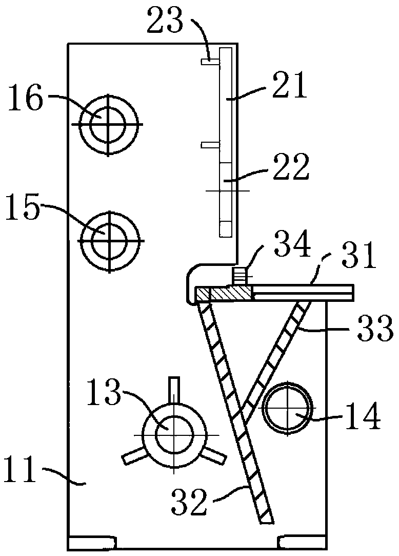
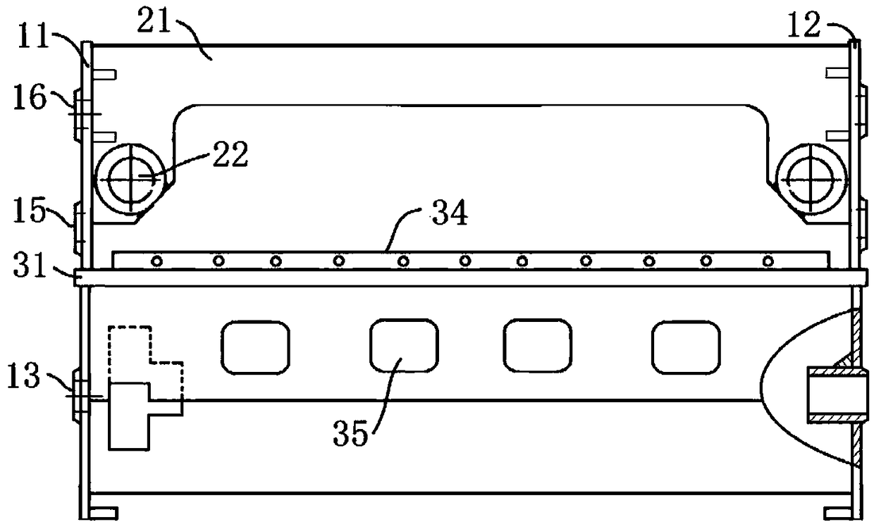
[0045] combine figure 1 , figure 2, a kind of mechanical shearing machine that adopts three-point support in this embodiment includes two wallboards arranged in parallel, and also includes a knife rest, a front panel 21 and a bracket, and the bracket is welded and connected to the bearing platform on the front side of the wallboard Above, the front panel 21 is welded and connected to the upper section of the front side of the wallboard, that is, the upper section on the side facing the workbench panel, and the main shaft hole 13 and the power shaft hole 14 are arranged on the wall board for installing the main shaft and connecting the drive of the motor axis. The wallboard is also provided with a lower roller shaft hole 15 and an upper roller shaft hole 16, and the lower roller shaft hole 15 and the upper roller shaft hole 16 are located on the same vertical line for installing rollers; the two ends of the front panel 21 are provided with protruding Section, the protruding ...

Embodiment 2

[0048] A mechanical shearing machine that adopts three-point support in this embodiment has the same basic structure as that of Embodiment 1, furthermore: the axis of the horizontal roller shaft hole 22 is located between the lower roller shaft hole 15 and the upper roller shaft hole 16 On the central symmetrical plane, that is, the distances between the lower roller shaft hole 15 and the upper roller shaft hole 16 are equal to the horizontal roller shaft hole 22 , it has better structural stability.

Embodiment 3

[0050] combine Figure 4 , for the mechanical shearing machine of embodiments 1-2, the present embodiment provides a processing method of a mechanical shearing machine using three-point support, and the processing steps are:

[0051] Step 1. Fix the first wallboard 11 and the second wallboard 12 together with bolts, machine the main shaft hole 13 and the power shaft hole 14 to the required size with a machine tool; then process the lower roller shaft hole 15 and the upper roller shaft hole 16, Reserve a margin of 2mm for the aperture; process the horizontal roller shaft hole 22 on the front panel 21, and reserve a margin of 2mm.

[0052] Step 2. Weld the workbench panel 31, the main support plate 32, and the auxiliary support plate 33 together to form a bracket, and then process the work surface of the workbench panel 31, reserving a margin of 0.5-2 mm, and this embodiment uses a margin of 1 mm .

[0053] combine image 3 , the main support plate used is welded with a knife...


PUM


Abstract

The invention discloses a machining method for a mechanical plate shearing machine and belongs to the field of plate shearing machines. According to the mechanical plate shearing machine, the lower end of a front panel is provided with a protruding section, roller shaft holes are machined in a wall plate and a front panel, and a three-point supporting structure is applied to the mechanical plate shearing machine. The main machining method for the plate shearing machine comprises the steps that the roller shaft holes in the wall plate and the front panel are machined, next, a main shaft and a drive shaft are installed, then, the front panel and a bracket are welded and installed, integrated machining is carried out on an installed rack, the size precision of the roller shaft holes is guaranteed, and finally machining and installation of other components are carried out. By means of the machining method, the problem that a traditional mechanical plate shearing machine is heavy in abrasion is solved, by means of control over the machining sequence and a process, the size precision of the rack is improved, the product machining quality of the plate shearing machine is advantageously improved, and the service life of the plate shearing plate is advantageously prolonged.

Description

technical field [0001] The invention relates to the technical field of shearing machines, and more specifically relates to a mechanical shearing machine with three-point support and a processing method thereof. Background technique [0002] According to the power type, the shearing machine is divided into hydraulic shearing machine and mechanical shearing machine. The hydraulic shearing machine mainly relies on two hydraulic cylinders to drive the movement of the upper tool holder, so as to realize the shearing of the plate. It has stable performance, but the processing efficiency Low; the mechanical shearing machine is driven by a motor, and the knife holder moves up and down along the slide rail. The mechanical shearing machine has sufficient power and high efficiency, but the knife holder wears a lot and the noise is loud. Therefore, how to reduce the wear and tear of the tool rest of the mechanical shearing machine is a major problem to improve its performance. [0003]...

Claims


Application Information

Patent Timeline
Patent Type & Authority Patents(China)
IPC IPC(8): B23D15/08B23D33/02B23D35/00B23P15/00
CPCB23D15/08B23D33/02B23D35/00B23P15/00
Inventor 王大进严长贵
Owner 安徽金大进重工机床有限公司
Learn More