Self-restrained explosive welding device with high energy utilization rate

An explosive welding, high-energy technology, applied in welding equipment, non-electric welding equipment, metal processing equipment, etc., can solve the problems of low energy utilization rate of explosives, safety of composite board flying, hidden dangers, etc., to achieve reasonable energy utilization rate of explosives, improve Energy utilization, the effect of reducing usage

Pending Publication Date: 2017-05-31
UNIV OF SCI & TECH OF CHINA
View PDF4 Cites 7 Cited by
  • Summary
  • Abstract
  • Description
  • Claims
  • Application Information

AI Technical Summary

Problems solved by technology

[0003] The purpose of the present invention is to design a self-constrained explosive welding device with high energy utilization rate in view of the low ener

Method used


Image

  • Self-restrained explosive welding device with high energy utilization rate
  • Self-restrained explosive welding device with high energy utilization rate
  • Self-restrained explosive welding device with high energy utilization rate

Examples


Example Embodiment

[0024] Example 1

[0025] For stainless steel and steel and explosive composite, the substrate is steel, the size is: 4000mm×2000mm×20mm; the double plate is stainless steel, the size is 4000mm×2000mm×3mm.

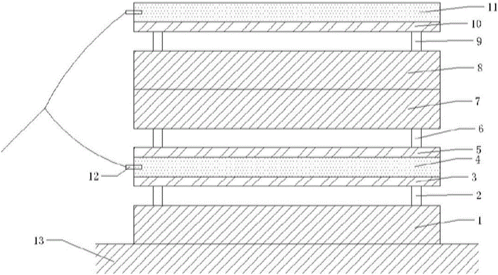
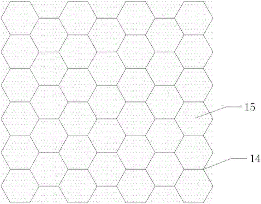
[0026] see figure 1 , this embodiment contains a group of double-sided welding combinations and a group of single-sided welding combinations. In the double-sided welding combination, the substrate A (1) is placed flat on the foundation (13) and the support column A (2) is evenly arranged on its upper surface, and the support column is rolled from a thin aluminum sheet. Wall thickness 0.5mm, height 8mm. According to the MTS test, a single support column can carry 1.2KN, and the estimated total load required is about 32KN, so 4 support columns are arranged per unit area, that is, 4×8×1.2=38.4KN>32KN; the first structural explosive ( 4) Its upper and lower surfaces are closely attached to doubler board A (3) and doubler board B (5), and the first structural explosive is co...

Example Embodiment

[0028] Example 2

[0029] For the explosive cladding of stainless steel and aluminum, the base plate is stainless steel, the size is: 400mm×400mm×28mm; the double plate is aluminum, the size is 400mm×400mm×4mm.

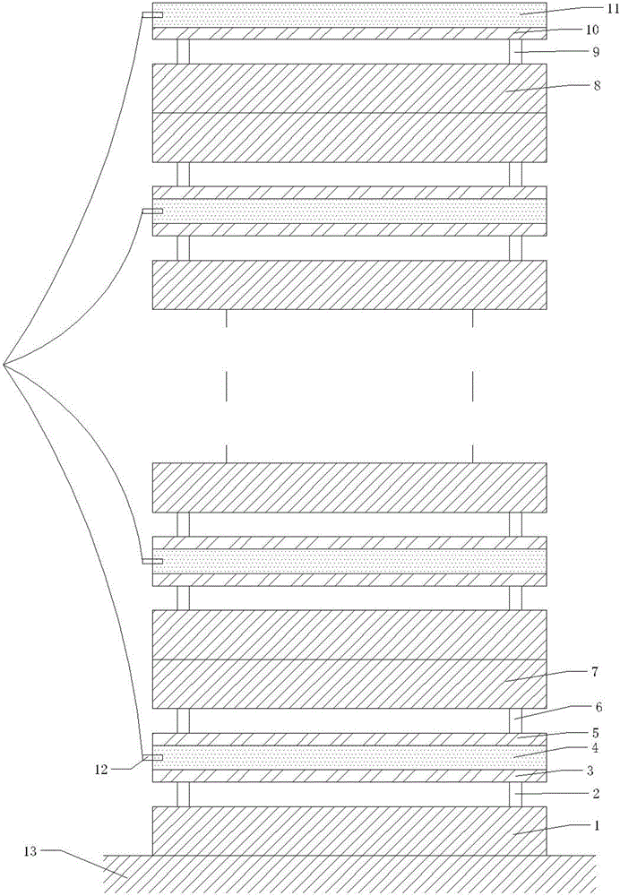
[0030] see image 3 , this embodiment contains n groups of double-sided welding combinations and a group of single-sided welding combinations. The double-sided welding combination is stacked sequentially from bottom to top, and the single-sided explosive welding combination is stacked on the uppermost substrate of the double-sided welding combination. The height of the supporting columns of each layer is 10mm high, and the number is determined by the bearing weight. The structural explosive is composed of honeycomb aluminum and powdered ammonium nitrate, and the height of the explosive is 22mm. The detonator is placed at the middle point of the left end of each layer of explosive and detonated simultaneously.

[0031] After the explosive is detonated, the composite...


PUM

PropertyMeasurementUnit
Wall thicknessaaaaaaaaaa
Radiusaaaaaaaaaa
Heightaaaaaaaaaa

Abstract

The invention discloses a self-restrained explosive welding device with a high energy utilization rate. The device comprises one or more double-side explosive welding combinations and a single-side welding combination. When explosives blast, the whole device is in a self-restrained state, movement of all composite plates is limited mutually, the hot potato that composite plates fly apart during double-side explosive compositing is perfectly solved, and the safety of field operation is improved. Compared with traditional explosive welding method, explosive energy utilization is more reasonable, the explosive using amount is greatly reduced, the cost is reduced, meanwhile, shockwave energy transmitted to air is reduced, and the noise pollution is remarkably reduced. In addition, the designed device can composite the multiple composite plates on one foundation at a time, and the explosive field can be saved, and the working efficiency can be improved.

Description

technical field [0001] The invention belongs to the technical field of explosive welding, in particular to a self-constrained explosive welding device with high energy utilization rate. Background technique [0002] Explosive compounding is a technology that uses the powerful shock wave generated by explosive explosion to make the cladding metal and the base metal collide at a high speed obliquely to generate a jet, clean the surface to be welded, and achieve metallurgical bonding of the base cladding. The explosive composite material combines the advantages of two or more metal materials, so its performance is excellent. And compared with other composite materials, the explosive composite process is simple, does not require expensive experimental equipment and fine manual operation, so the cost of explosive composite materials is low. After decades of development, explosive recombination between almost all metals can now be realized. Its products are widely used in industr...

Claims


Application Information

Patent Timeline
IPC IPC(8): B23K20/08
CPCB23K20/08
Inventor 马宏昊杨明沈兆武王奕鑫周国安
Owner UNIV OF SCI & TECH OF CHINA
Why Eureka
Try Eureka