A metal wire drawing machine

A wire drawing machine and metal technology, which is applied to metal processing equipment, grinding machine parts, grinding workpiece supports, etc., can solve the problems of accelerated spindle bearing wear, cumbersome maintenance, and reduced processing accuracy of wire drawing machines. Longevity, the effect of reducing maintenance difficulty and cost

Active Publication Date: 2019-09-10
珠海市圆方锡工艺技术研发有限公司
View PDF7 Cites 0 Cited by
  • Summary
  • Abstract
  • Description
  • Claims
  • Application Information

AI Technical Summary

Problems solved by technology

The vacuum suction sucks the particles in the working environment into the main shaft bearing, which accelerates the wear of the main shaft bearing, thus causing the shaking of the main shaft, resulting in the reduction of the processing accuracy of the wire drawing machine, and the frequent replacement of the main shaft bearing at the same time
When replacing the main shaft bearing, it is necessary to remove the main shaft connected to the main shaft bearing, the main shaft pulley and other parts together. After reassembly, the main shaft needs to be calibrated, which is cumbersome to maintain

Method used


Image

  • A metal wire drawing machine
  • A metal wire drawing machine
  • A metal wire drawing machine

Examples


Embodiment 1

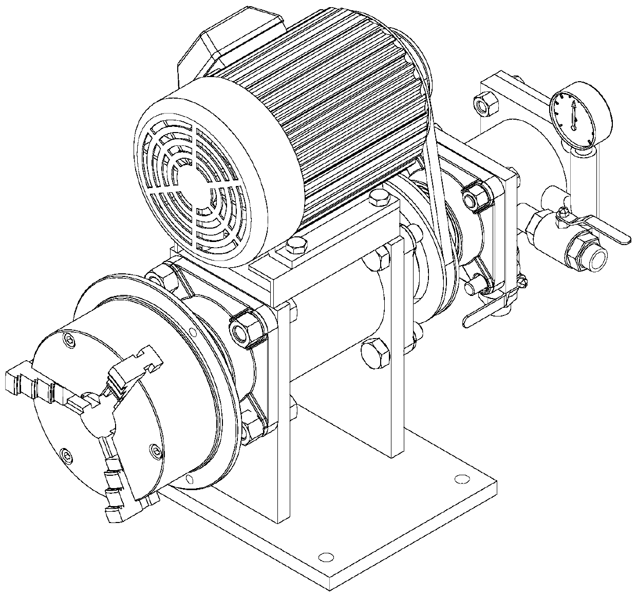
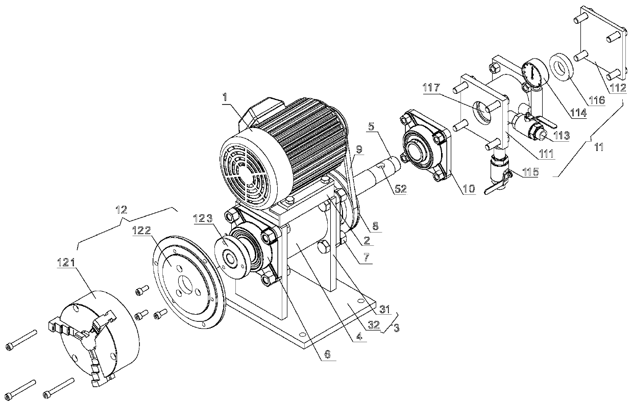
[0028] like figure 1 , the metal wire drawing machine in this embodiment includes a motor 1, a motor base 2, a main shaft base 3, a main shaft cavity housing 4, a main shaft 5, a left main shaft bearing 6, a right main shaft bearing 7, a main shaft pulley 8, and a belt 9, Vacuum chamber bearing 10, vacuum chamber assembly 11, clamping assembly 12.

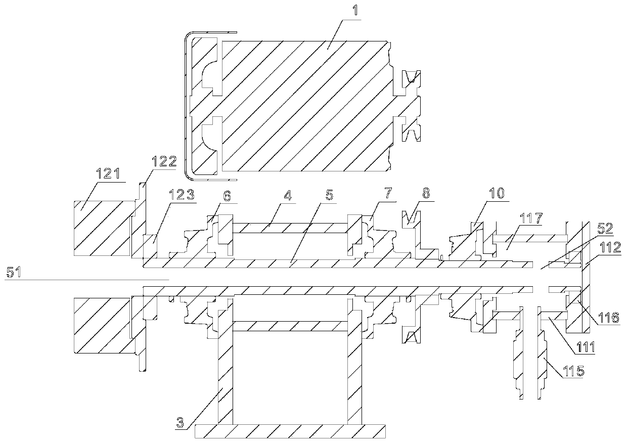
[0029] The spindle base 3 includes two vertical plates 31 and a horizontal bottom plate 32 , and the two vertical plates 31 are arranged above the horizontal bottom plate 32 and fixedly connected with the horizontal bottom plate 32 . The main shaft cavity housing 4 is arranged between two vertical plates 31 and is fixedly connected with the vertical plates 31 . The main shaft cavity housing 4 is cylindrical, and the main shaft cavity is formed inside. The shaft center of the main shaft 5 is provided with a main shaft longitudinal hole 51, and the right end of the main shaft 5 is radially provided with a main shaft transverse hole...

Embodiment 2

[0036] The structure of the metal wire drawing machine in this embodiment is substantially the same as that in Embodiment 1, except that the clamping assembly 12' includes a vacuum suction cup 121', a suction cup flange 122' and a main shaft flange 123'. The main shaft flange 123' is sleeved on the main shaft 5' and is located at the left end of the left main shaft bearing 6'. The suction cup flange 122' is set on the main shaft 5', is set on the main shaft flange 123' and is fixedly connected with it. The vacuum suction cup 122' is sleeved on the main shaft 5' and fixedly connected with the suction cup flange 121'.

[0037] After the vacuum valve 113' is connected to the vacuum pump (not shown), close the sewage valve 115', open the vacuum valve 113', and form a vacuum suction force outside the vacuum chuck 122', which can absorb the workpiece and carry out wire drawing.


PUM


Abstract

A novel metal wire drawing machine comprises a spindle base, a spindle cavity shell, a spindle, a left spindle bearing, a right spindle bearing, a vacuum cavity bearing, a vacuum cavity assembly and a clamping assembly. The spindle base comprises two vertical plates and a horizontal bottom plate. The two vertical plates are arranged above the horizontal bottom plate and fixedly connected with the horizontal bottom plate. The spindle cavity shell is arranged between the two vertical plates and fixedly connected with the vertical plates. A spindle longitudinal hole is formed in the axis of the spindle. A spindle transverse hole penetrating a spindle body is formed in the right end of the spindle in the radial direction. The spindle horizontally penetrates the spindle cavity shell and is fixed by the left spindle bearing and the right spindle bearing on the outer surfaces of the vertical plates. The spindle is sleeved with the vacuum cavity bearing. The vacuum cavity bearing is arranged on the right side of a spindle belt wheel. The spindle is sleeved with the vacuum cavity assembly. The vacuum cavity assembly is arranged at the right end of the vacuum cavity bearing and fixedly connected with the vacuum cavity bearing. The clamping assembly is arranged on the left side of the left spindle bearing and capable of clamping external machining parts through vacuum adsorption or a clamping disc.

Description

[0001] 【Technical field】 [0002] The invention relates to the field of mechanical parts processing equipment, in particular to a machine for the wire drawing process of metal parts. [0003] 【Background technique】 [0004] If the appearance of metal products is to show a uniform filament texture effect, it needs to be fixed on the rotating shaft of the corresponding processing equipment during processing, and then its surface is continuously polished with sandpaper or other abrasive materials. The traditional wire drawing machine uses the spindle chamber of the wire drawing machine as a vacuum chamber, and the spindle bearings arranged before and after the vacuum chamber need to bear the dual loads of rotation and vacuum pressure during machining. The vacuum suction sucks the particles in the working environment into the main shaft bearing, which accelerates the wear of the main shaft bearing, thus causing the shaking of the main shaft, resulting in the reduction of the proces...

Claims


Application Information

Patent Timeline
Patent Type & Authority Patents(China)
IPC IPC(8): B24B41/04B24B41/06
Inventor 方宣平罗游
Owner 珠海市圆方锡工艺技术研发有限公司
Why Eureka
Try Eureka