Six-axis robot

A six-axis robot and reducer technology, applied in the field of manipulators, can solve the problems of incapability of mass production and widespread promotion, single function of manipulators, limited moving range, etc., to avoid joint motion jitter, low maintenance costs, and reduce production costs.

Pending Publication Date: 2017-05-31
昆山威创自动化科技有限公司
View PDF9 Cites 4 Cited by
  • Summary
  • Abstract
  • Description
  • Claims
  • Application Information

AI Technical Summary

Problems solved by technology

[0003] However, at present, the manipulators in the domestic market are common problems such as complex structure, low transmission efficiency, unstable control, and limited moving range, which make the manipulators in industrial production relatively single-function and high in production cost, and cannot be mass-produced and widely used. to promote

Method used


Image

  • Six-axis robot
  • Six-axis robot
  • Six-axis robot

Examples


Embodiment 1

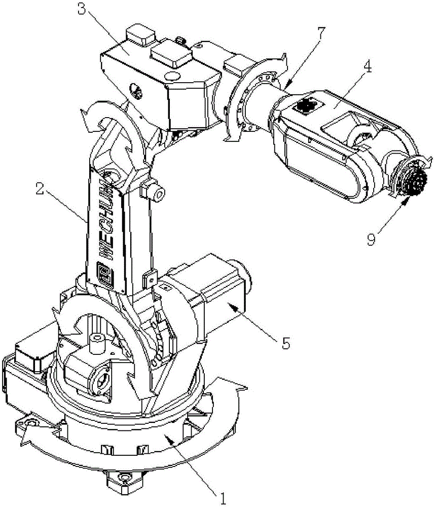
[0065] See attached Figure 1~4 As shown in FIG. 1 , the three-dimensional structure schematic diagram, the front view structural schematic diagram and the side view structural schematic diagram of the first embodiment of the six-axis robot in the present invention are respectively shown. The six-axis robot includes a rotating base 1, a swing arm 2, a receiving base 3, a swing head 4, a first swing drive mechanism 5, a second swing drive mechanism 6, a rotation drive mechanism 7, a third swing drive mechanism 8, and An end effector 9 for receiving the grabbing assembly and driving the grabbing assembly to rotate (the grabbing assembly can use vacuum chucks, pneumatic grippers, or electromagnets), wherein the swing arm 2 is vertically arranged on the rotating on the base 1, and can rotate horizontally under the drive of the rotating base 1; the first swing driving mechanism 5 is also arranged on the rotating base 1, and the first swing driving mechanism 5 can also drive the Th...

Embodiment 2

[0077] See attached Figures 12 to 15 As shown, the three-dimensional structure schematic diagram, the front view structural schematic diagram and the side view structural schematic diagram of the second embodiment of the six-axis robot of the present invention are respectively shown.

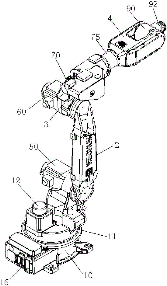
[0078] The difference between the six-axis robot shown in Embodiment 2 and the six-axis robot shown in Embodiment 1 mainly lies in: the appearance shape is different, and the assembly method between the rotary drive mechanism and the swing head is different (refer to the attached Figure 16 shown); the structure of the remaining parts / mechanisms in the six-axis robot shown in Embodiment 2, and the connection relationship and action principle between the remaining parts / mechanisms are all the same as in Embodiment 1.

Embodiment 3

[0080] See attached Figures 17-20 As shown, the three-dimensional structure schematic diagram, the front view structural schematic diagram and the side view structural schematic diagram of the third embodiment of the six-axis robot of the present invention are respectively shown.

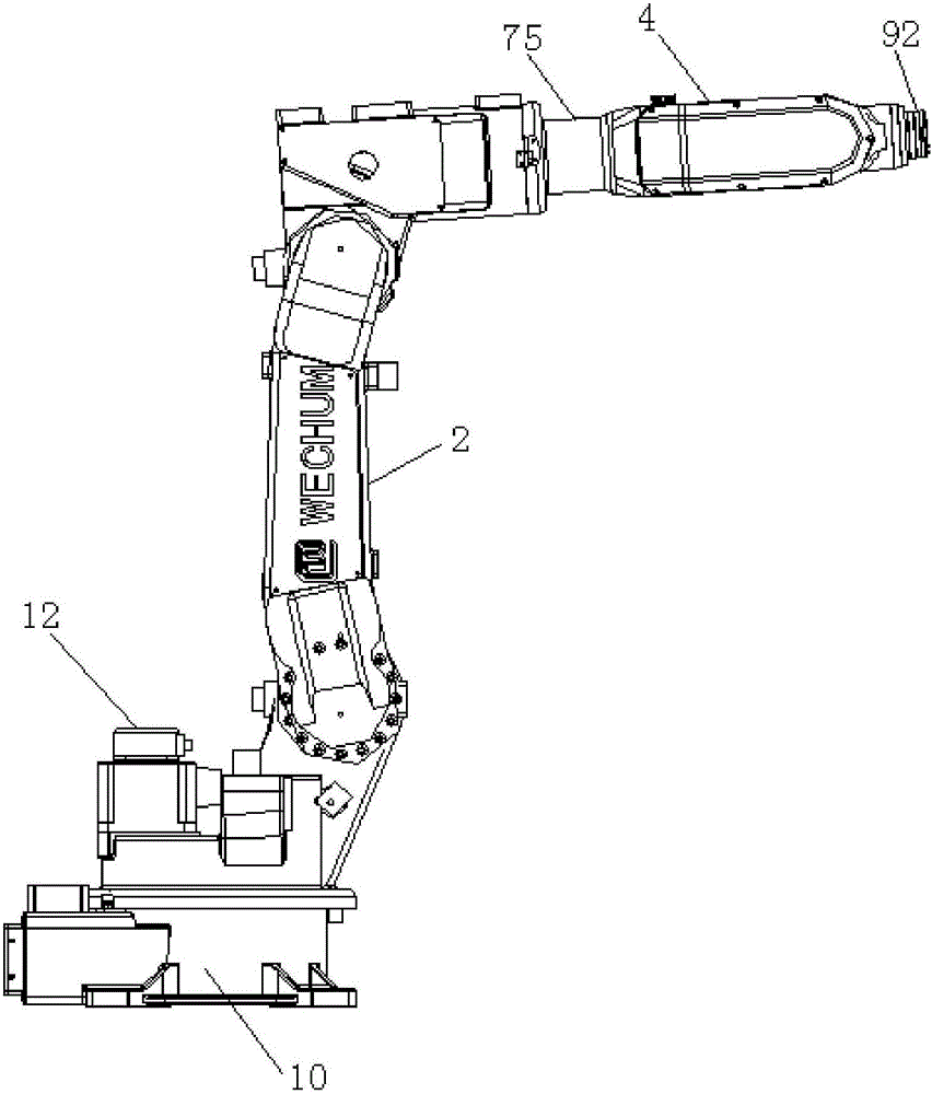
[0081] The difference between the six-axis robot shown in Embodiment 3 and the six-axis robot shown in Embodiment 1 mainly lies in the difference in appearance and shape, and the difference in the assembly method between the second swing driving mechanism and the receiving seat (refer to the attached Figure 21 shown), and the assembly method between the rotary drive mechanism and the swing head is different (refer to the attached Figure 22 shown); the structure of the remaining parts / mechanisms in the six-axis robot shown in Embodiment 3, and the connection relationship and action principle between the remaining parts / mechanisms are all the same as in Embodiment 1.

[0082] To sum up, compared w...


PUM


Abstract

The invention discloses a six-axis robot which comprises a rotating seat, a swing arm, a bearing seat, a swing head, a first swing driving mechanism, a second swing driving mechanism, a rotating driving mechanism, a third swing driving mechanism and an end executing mechanism. The swing arm is vertically arranged on the rotating seat and can be driven by the rotating seat to horizontally rotate. The firsts swing driving mechanism is arranged on the rotating seat and can drive the swing arm to swing front and back. The bearing seat is arranged on the upper side of the swing arm, the second swing driving mechanism is arranged on the bearing seat, and the swing head is arranged on the bearing seat through the rotating driving mechanism. The second swing driving mechanism can drive the bearing seat to move, so that the swing head vertically swings, and the rotating driving mechanism can drive the swing head to rotate. The third swing driving mechanism and the end executing mechanism are both arranged on the swing head, and the third swing driving mechanism can drive the end executing mechanism to vertically swing. The six-axis robot is high in transmission precision, stable in operation and capable of effectively avoiding the situation of joint movement shaking.

Description

technical field [0001] The invention relates to the technical field of manipulators, and specifically provides a six-axis robot. Background technique [0002] A manipulator is an automatic operating device that can imitate certain movement functions of the human hand and arm, and is used to grab, carry objects or operate tools according to a fixed program. It can replace human heavy labor to realize mechanization and automation of production, and can operate in harmful environments to protect personal safety, so it is widely used in machinery manufacturing, metallurgy, electronics, light industry and atomic energy departments. [0003] However, at present, the manipulators in the domestic market are common problems such as complex structure, low transmission efficiency, unstable control, and limited moving range, which make the manipulators in industrial production relatively single-function and high in production cost, and cannot be mass-produced and widely used. promote. ...

Claims


Application Information

Patent Timeline
Patent Type & Authority Applications(China)
IPC IPC(8): B25J9/00B25J9/10
CPCB25J9/00B25J9/10
Inventor 张世宏
Owner 昆山威创自动化科技有限公司
Why Eureka
Try Eureka