Robot accuracy compensation method synthesizing pose error model and rigidity compensation

An error model and precision compensation technology, applied in the field of robot calibration, can solve problems such as low efficiency and complicated process, and achieve the effect of improving online work efficiency and eliminating the calculation and derivation process

Active Publication Date: 2017-05-31
NANJING UNIV OF SCI & TECH
View PDF5 Cites 55 Cited by
  • Summary
  • Abstract
  • Description
  • Claims
  • Application Information

AI Technical Summary

Problems solved by technology

The process is complicated and the efficiency is low

Method used


Image

  • Robot accuracy compensation method synthesizing pose error model and rigidity compensation
  • Robot accuracy compensation method synthesizing pose error model and rigidity compensation
  • Robot accuracy compensation method synthesizing pose error model and rigidity compensation

Examples


Embodiment Construction

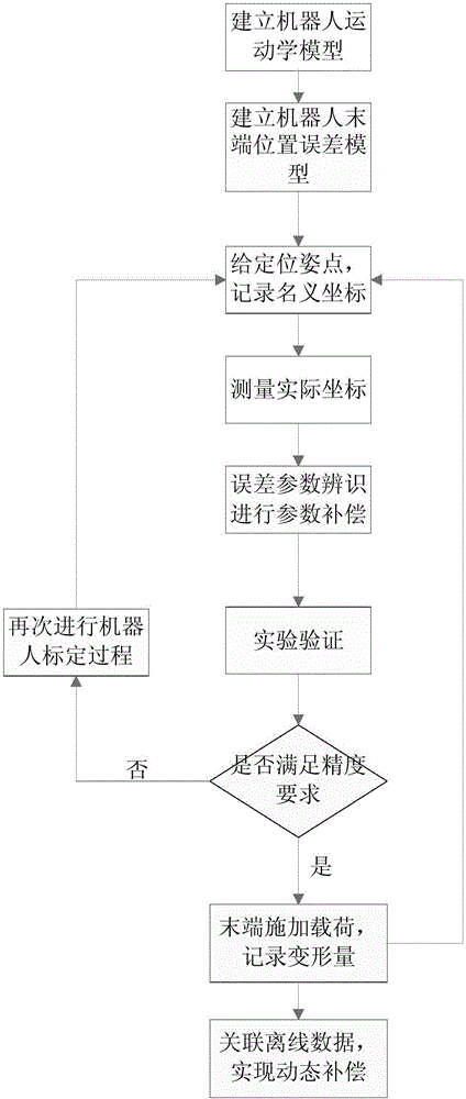
[0045] to combine figure 1 , figure 2 , a kind of robot precision compensation method of comprehensive pose error model and stiffness compensation of the present invention, comprises the following steps:

[0046] Step 1. Establish a robot motion model according to the structural parameters of the robot; specifically:

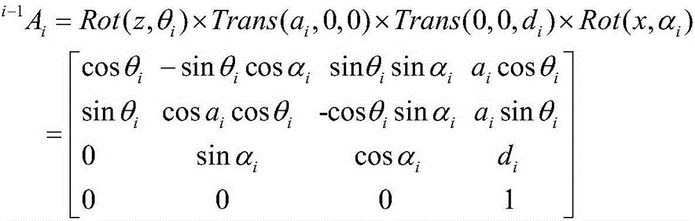
[0047] Step 1-1, establish the homogeneous transformation matrix between adjacent joints of the robot according to the DH method, the matrix is:

[0048]

[0049] In the above formula, a i is the connecting rod length, α i is the joint torsion angle, d i is the connecting rod offset, θ i is the joint rotation angle, X is the X axis of the link coordinate system, and Z is the Z axis of the link coordinate system.

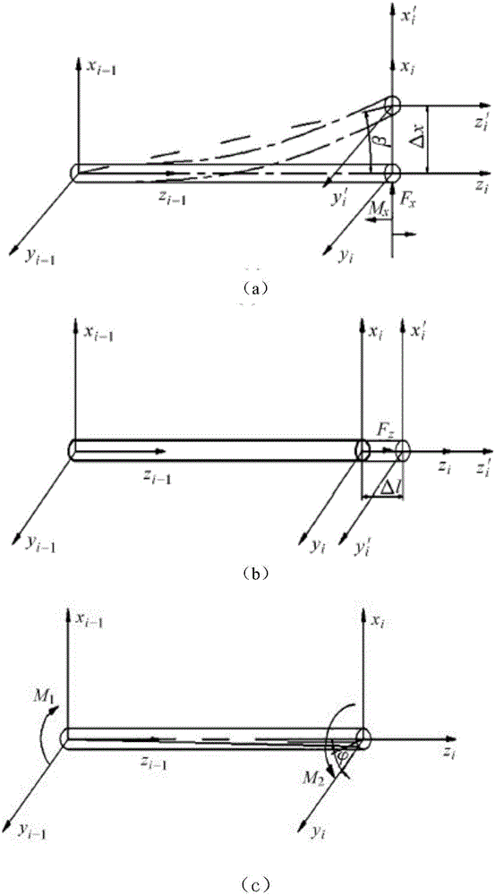
[0050] Step 1-2. Introduce the rotation Rot(y, β) around the y-axis to the homogeneous transformation matrix established in step 1-1, and eliminate the singularity between the intermediate links when the axes are parallel or nearly parallel. ...


PUM


Abstract

The invention discloses a robot accuracy compensation method synthesizing a pose error model and rigidity compensation. The method comprises the following steps: step 1, establishing a robot motion model according to structural parameter of a robot; step 2, establishing a robot error model; step 3, in a robot working space, randomly giving a target pose point, and when a tail end of the robot moves a designated point, recording a joint angle at the moment; step 4, using a position measuring instrument to measure actual coordinates Pa of the given target pose point; step 5, using a least square method to recognize an error parameter; step 6, applying a load at the tail end of the robot, measuring the deformation amount of the robot, then returning to step 3, compensating a re-recognized structural error for the motion model again, thereby eliminating the pose error of the tail end due to the deformation caused by the load, and meanwhile, data of the deformation amount caused by the load is stored in a database for later accuracy compensation. According to the invention, the absolute positioning accuracy of the robot can be improved remarkably, and high simplicity and high efficiency are realized.

Description

technical field [0001] The invention belongs to the technical field of robot calibration, in particular to a robot precision compensation method which integrates pose error model and stiffness compensation. Background technique [0002] With the promulgation of "Made in China 2025 Outline", industrial robots will set off another development boom in our country. As an important index to measure the performance of industrial robots, accuracy includes repeat positioning accuracy and absolute positioning accuracy. Today's industrial robots have high repetitive positioning accuracy, but low absolute positioning accuracy, which is not conducive to off-line programming and high-precision machining. The robot kinematics calibration is an effective means to improve the positioning accuracy of the robot, which mainly includes four stages: modeling, measurement, identification, and compensation. [0003] The traditional method of robot calibration only compensates for errors caused b...

Claims


Application Information

Patent Timeline
Patent Type & Authority Applications(China)
IPC IPC(8): B25J19/00B25J9/16
Inventor 童一飞赵瑞文李东波吴绍锋谭清锰
Owner NANJING UNIV OF SCI & TECH
Why Eureka
Try Eureka