Inner hole laser marking equipment used for sucker rod coupling and marking method thereof

A technology of laser marking equipment and laser marking methods, applied in typewriters, printing, etc., can solve the problems of easy wear and tear of lettering, high manual labor intensity, and poor marking quality, so as to achieve protection traceability, improve production efficiency, The effect of simple structure

Inactive Publication Date: 2017-05-31
重庆亮科激光科技有限公司 +1
View PDF6 Cites 9 Cited by
  • Summary
  • Abstract
  • Description
  • Claims
  • Application Information

AI Technical Summary

Problems solved by technology

[0006] In order to solve the existing technical problems of low efficiency, poor marking quality, high labor intensity, and easy wear and tear of the lettering type on the outer circle of the coupling by mechanical means, the present invention provides a Inner hole laser marking equipment and marking method of rod coupling

Method used


Image

  • Inner hole laser marking equipment used for sucker rod coupling and marking method thereof
  • Inner hole laser marking equipment used for sucker rod coupling and marking method thereof
  • Inner hole laser marking equipment used for sucker rod coupling and marking method thereof

Examples


Embodiment 1

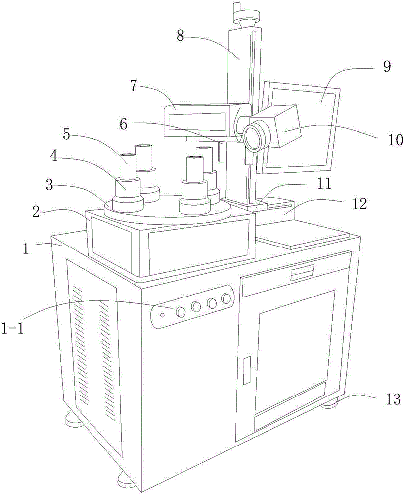
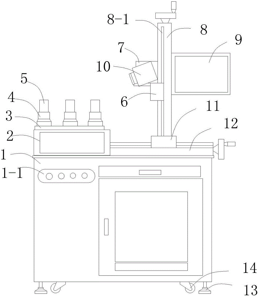
[0045] Such as Figures 1 to 3As shown, this embodiment provides a laser marking device for inner holes of sucker rod couplings, including an electric control cabinet 1, an intermittent divider 2 is arranged on the electric control cabinet 1, and a turntable is connected to the intermittent divider 2 3. The intermittent divider 2 controls the intermittent rotation of the turntable 3. On the turntable 3, there are a plurality of receiving sleeves 4 for installing the collar 5 to be marked evenly distributed on the circumference. The side of the intermittent divider 2 on the electric control cabinet 1 is provided with The horizontal guide rail 12 is connected with the vertical support 8 that can reciprocate along the horizontal guide rail 12 through the clip A11. The vertical support 8 is provided with a vertical guide rail groove 8-1, and the vertical support 8 One side is provided with a laser 7 that moves up and down along the vertical rail groove 8-1, and a rotating laser he...

Embodiment 2

[0050] This embodiment is further improved on the basis of Embodiment 1, specifically:

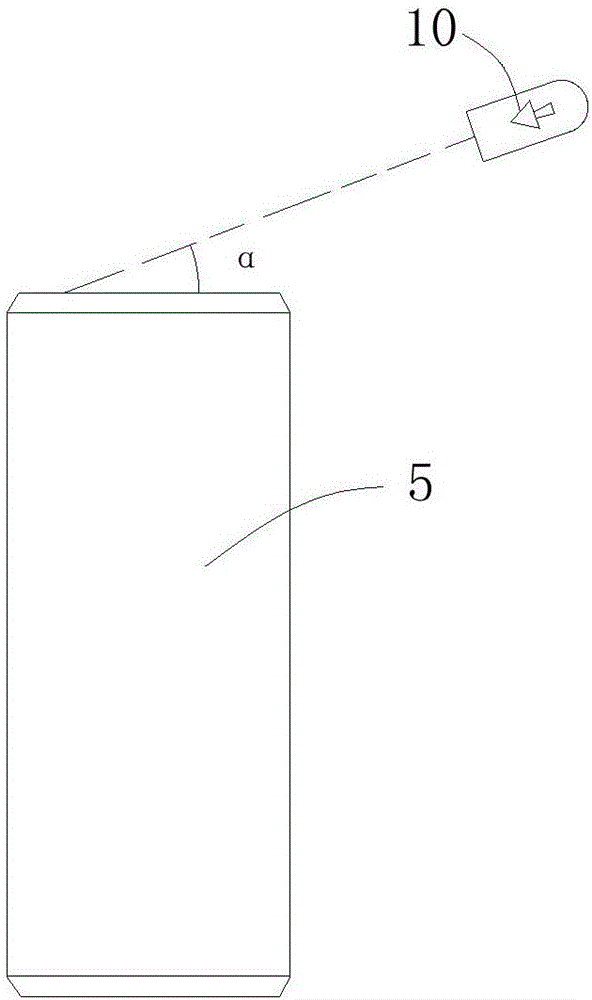
[0051] The rotating laser head 10 can rotate 360° around the laser 7 .

[0052] The number of said receiving sleeves 4 is four.

[0053] The laser adopts 100-200W fiber laser from Chongqing Liangke Laser Technology Co., Ltd.

Embodiment 3

[0055] This embodiment is further optimized on the basis of embodiment 1 or 2, specifically:

[0056] The receiving sleeve 4 is plug-fitted with the collar 5 to be marked, and three spring duck tongues are arranged in the receiving sleeve 4 to assist in pressing the collar 5 to be marked.

[0057] The receiving sleeve is mated with the coupling to be marked, and there are three spring duck tongues in the sleeve to assist in pressing the coupling to be marked. The built-in spring solves the problem caused by the slight difference in the outer diameter of the same model product. The clamping problem; the duck tongue provides an effective contact length in the axial direction, which ensures the automatic centering of product installation and increases the marking quality.


PUM


Abstract

The invention discloses inner hole laser marking equipment used for a sucker rod coupling and a marking method thereof, and relates to the technical field of laser marking. The inner hole laser marking equipment comprises an electric control cabinet and a laser. An indexing separator is arranged on the electric control cabinet. A rotary plate is connected to the indexing separator. A plurality of adapting sleeves used for mounting the marking coupling are evenly distributed on the rotary plate. A rotary laser head is movably connected to the laser. The inner hole laser marking equipment has the advantages that the structure is simple, the working efficiency is high, the labor intensity is low, inner hole marking of the to-be-marked coupling is facilitated, and marking characters are not liable to be abraded; during operation, the to-be-marked coupling is mounted on the adapting sleeves of the rotary plate, the position of the laser is adjusted, required marking parameters are input into a computer, the focal distance of the laser beamon the inner wall of the coupling is adjusted, then marking is started, the focal distance of the laser beams is adjusted, deep marking and carbonizing marking can be achieved, after marking of a product is completed, the rotary plate rotates automatically to another product for marking, and thus uninterrupted marking operation can be achieved.

Description

technical field [0001] The invention relates to the field of laser marking equipment, and more specifically relates to a laser marking equipment for inner holes of sucker rod couplings and a marking method thereof. Background technique [0002] The sucker rod is a slender rod of the pumping well, it is connected to the polished rod on the top, and the pump is connected to the bottom to transmit power. The length of a single sucker rod is 7.62 or 8 meters, 9.14m, and the material is generally low-carbon alloy steel after quenching and tempering treatment. According to the length requirements, the single sucker rods are connected one by one in the oil pipe with an internal thread coupling Get up and extend all the way to the piston at the underground reservoir. [0003] At present, the known marking method of API sucker rod couplings is to use outer circle rolling lettering, usually the combination of rollers, lettering templates and replaceable nails that can adjust the spac...

Claims


Application Information

Patent Timeline
Patent Type & Authority Applications(China)
IPC IPC(8): B41J2/435B41J3/407
CPCB41J2/435B41J3/4073
Inventor 代勇钟新梅寇向东
Owner 重庆亮科激光科技有限公司
Why Eureka
Try Eureka