

Failure-protecting decoupling-type braking mechanism and control method
A technology for fail-safe and braking mechanism
- Summary
- Abstract
- Description
- Claims
- Application Information
AI Technical Summary
Problems solved by technology
Method used
Image

Examples
Embodiment 1
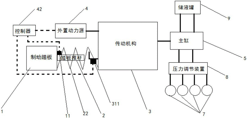
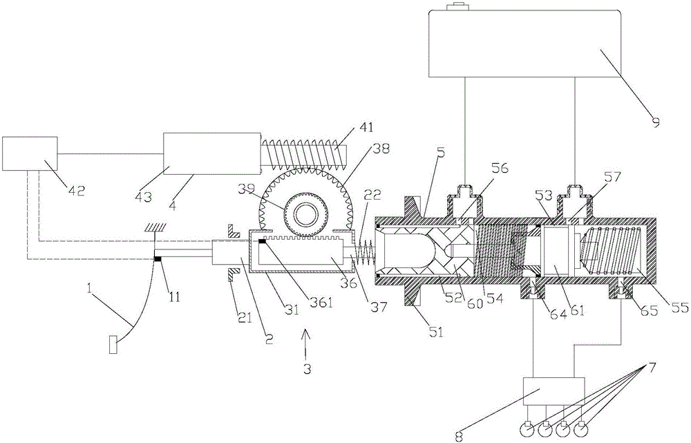
[0041] Such as Figures 1 to 6 shown. The invention discloses a failure protection decoupling brake mechanism, which includes a hydraulic tank 9, a master cylinder 5, a hydraulic adjustment device 8 and a wheel cylinder 7; The oil supply holes 56, 57, the two drain holes 64, 65 of the master cylinder 5 communicate with the wheel cylinder 7 through the hydraulic adjustment device 8 respectively; the failure protection decoupling type braking mechanism also includes a brake pedal 1, a brake Moving push rod 2, transmission mechanism 3 and external power source 4;
[0042] The external power source 4 is used to provide rotational torque to the transmission mechanism 3, and the brake pedal 1 is movably connected to the brake push rod 2;
[0043] The transmission mechanism 3 includes a worm gear 38 and a gear 39 coaxially installed therewith, a rack 36 and a decoupling sleeve 31 sleeved on the outside of the rack 36; the upper teeth of the rack 36 mesh with the gear 39; The left ...
Embodiment 2
[0061] This embodiment is the same as Embodiment 1 except for the following features.
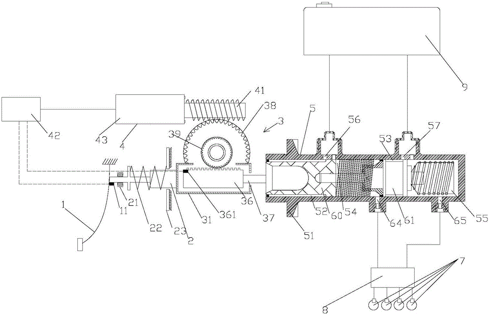
[0062] The specific installation position of the return spring 22 is sleeved on the brake push rod 2, one end of which is connected to the baffle plate 23 arranged in the middle of the brake push rod 2, and the other end is offset against the limit plate on the right side of the brake push rod 2 ; The baffle 23 is not in contact with or in sliding contact with the brake push rod 2; when the brake pedal 1 is reciprocated, the brake push rod 2 can drive the decoupling sleeve 31 to reciprocate axially.
Embodiment 3
[0064] This embodiment is the same as Embodiment 1 except for the following features.
[0065] The specific installation position of the return spring 22 is that one end is in contact with the inner wall of the decoupling sleeve 31, and the other end extends out of the right end opening of the decoupling sleeve 31, and is in contact with the master cylinder shell 51 of the master cylinder 5; When the pedal is 1, the brake push rod 2 can drive the decoupling sleeve 31 to reciprocate axially.
PUM
 Abstract
Description
Claims
Application Information