Winding machine

A technology of a winder and a frame, applied in the field of winders, can solve problems such as affecting the quality and stability of winding yarn, large yarn resistance, affecting product quality, etc., to achieve stable conveying, improve product quality, and reduce pulling Effect

Pending Publication Date: 2017-05-31
XINCHANG WANSHIFA TEXTILE MACHINERY
View PDF9 Cites 11 Cited by
  • Summary
  • Abstract
  • Description
  • Claims
  • Application Information

AI Technical Summary

Problems solved by technology

If these processes directly use bobbins or skeins, it will cause too much downtime, affect production efficiency, and also affect product quality. Therefore, increasing the package capacity is a necessary condition for improving the productivity and quality of subsequent processes.
The existing winding machines are driven by the motor to rewind the placed skein or bobbin. The skein and bobbin are directly placed on the unwinding structure. The most common way is to insert the bobbin on the column. First, put the skein on a shelf, and the motor drives the main reel to make the skein or bobbin passively rotate to complete unwinding. The resistance to pulling the yarn is relatively large, which affects the quality of the yarn and is passive. The way of rotation cannot achieve a higher speed of the motor, and speeding up the speed will affect the quality and stability of the winding yarn

Method used


Image

  • Winding machine
  • Winding machine
  • Winding machine

Examples


Embodiment Construction

[0020] Specific embodiments of the present invention will be described in detail below in conjunction with the accompanying drawings.

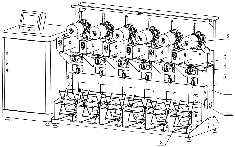
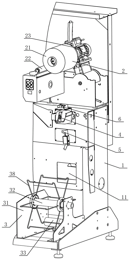
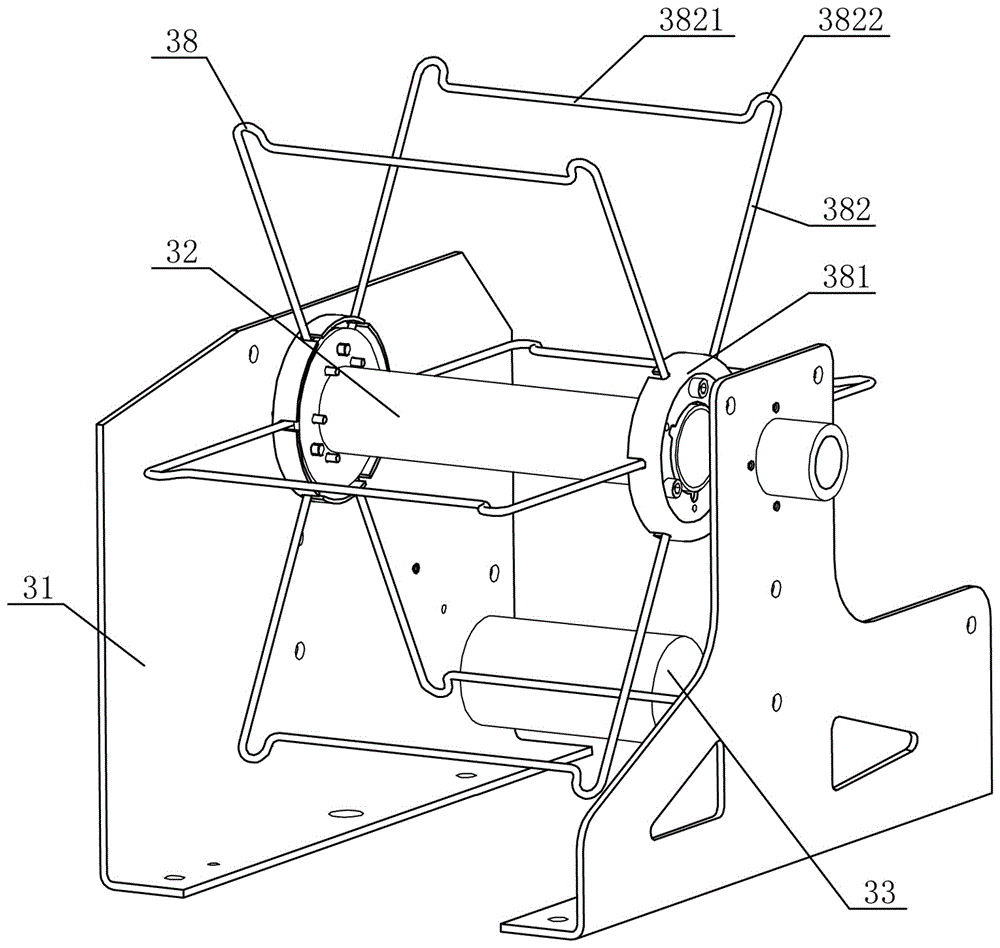
[0021] Such as Figure 1-7 Shown is the specific embodiment of the winder of the present invention. This embodiment includes a frame 1, a main winding mechanism 2 and an active unwinding mechanism 3, the main winding mechanism 2 and the active unwinding mechanism 3 are arranged in multiple groups side by side and are respectively located in the upper and lower fronts of the frame 1; the active unwinding mechanism Mechanism 3 includes mounting bracket 31, rotating shaft 32, unwinding motor 33 and top disc 34, two top discs 34 are rotatably arranged on the mounting brackets 31 on both sides, and rotating shaft 32 is driven from both sides by top disc 34 on both sides. Responding to the positioning, one side of the top plate 34 is connected to the unwinding motor 33, and the rotating shaft 32 is arranged parallel to the frame 1. On the rotating ...


PUM


Abstract

The invention discloses a winding machine. An unwinding motor of an active unwinding mechanism and a main winding motor of a main winding mechanism of the winding machine work simultaneously at the same speed. Yarn is unwound actively by hank holders or bobbin crades on a rotary shaft, and the yarn which is oiled and lubricated by an oiling device is wound by an active winding wheel. When the hank holders or the bobbin crades are driven by the rotary shaft to rotate, longitudinal wind is generated and blown into a hollowed-out opening, and thus, internal heat dissipation is conducted. According to the winding machine, the unwinding motor is additionally arranged to cooperate with the main winding motor of the winding machine so that the unwinding motor and the main winding motor can work together, the speeds of the two motors are kept identical, active unwinding in the positions of the hank holders or the bobbin crades and active winding in the position of a winding core are conducted simultaneously, pulling on the yarn is reduced, the quality of the yarn can be guaranteed, and the yarn is not prone to being damaged; and conveying is more stable, and shifting is not prone to occurring. Through the active unwinding mode, higher rotation speeds can be selected for both the unwinding motor and the winding motor, due to the fact that the resistance of the yarn is reduced, the yarn is prevented from being damaged, both unwinding and winding can be kept stable, the working efficiency of the winding machine is improved, and the product quality is improved.

Description

technical field [0001] The invention relates to a spinning machine, in particular to a winding machine. Background technique [0002] The main function of the winding machine is to connect bobbins or skeins with less capacity through winding to make a bobbin with a larger capacity. Weft yarn and knitting yarn etc. If these processes directly use bobbins or skeins, it will cause too much downtime, affect production efficiency, and also affect product quality. Therefore, increasing the package capacity is a necessary condition for improving the productivity and quality of subsequent processes. The existing winding machines are driven by the motor to rewind the placed skein or bobbin. The skein and bobbin are directly placed on the unwinding structure. The most common way is to insert the bobbin on the column. First, put the skein on a shelf, and the motor drives the main reel to make the skein or bobbin passively rotate to complete unwinding. The resistance to pulling the ya...

Claims


Application Information

Patent Timeline
Patent Type & Authority Applications(China)
IPC IPC(8): B65H54/02B65H49/34B65H49/36B65H63/00B65H71/00
CPCB65H49/34B65H49/36B65H54/023B65H63/00B65H71/00B65H2701/31
Inventor 徐属斌王伟军
Owner XINCHANG WANSHIFA TEXTILE MACHINERY
Why Eureka
Try Eureka