Method and structure for connection of heat preservation system and wall of building

A technology for building thermal insulation and walls, applied in building structures, building components, thermal insulation, etc., can solve problems such as loss of compression and anchoring effect of expansion bolts, broken plates around the pressed sheet, and easy fires, etc., so as to save materials and labor , Pollution reduction, and easy operation

Inactive Publication Date: 2017-05-31
王杏林
View PDF2 Cites 0 Cited by
  • Summary
  • Abstract
  • Description
  • Claims
  • Application Information

AI Technical Summary

Problems solved by technology

The disadvantages of this structure are: 1. Not durable
2. Prone to fire
Due to the looseness, low strength and small rigidity of the plate, under the pulling effect of the negative wind pressure on the plate, the plate is often broken along the periphery of the pressing sheet, and a cavity is formed on the plate, so that the expansion bolt loses the compression and anchoring effect on the plate.
Sometimes even when the expansion bolts are tightened during construction, the surrounding plates of the pressing sheet are crushed and broken

Method used


Image

  • Method and structure for connection of heat preservation system and wall of building
  • Method and structure for connection of heat preservation system and wall of building

Examples


Embodiment 1

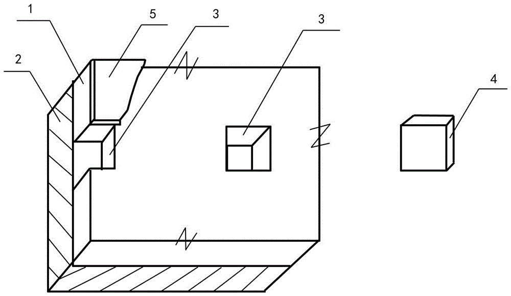
[0031] The blocking board 4 is a wooden board that has been treated with anticorrosion and fire prevention. Fill the blocking board 4 into the window hole 3, and fix the blocking board 4 on the wall with expansion bolts or a nail gun; or fix the blocking board 4 on the wall with an adhesive . The protective layer laid on the outside of the thermal insulation layer is fixed by means of the blocking plate 4 again.

Embodiment 2

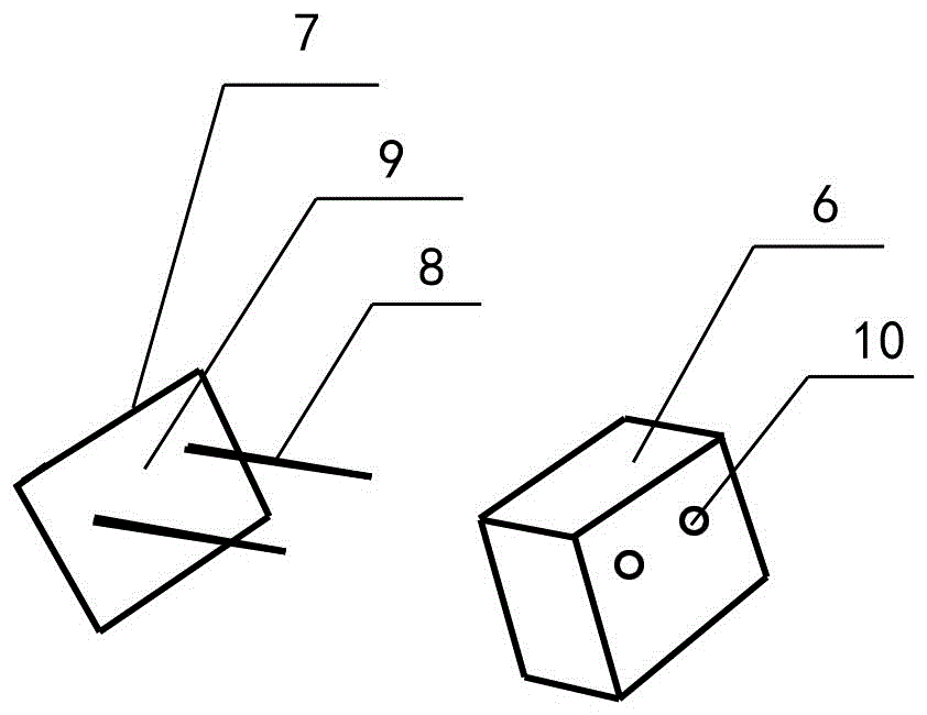
[0033] Connect one end of the steel wire or bolt 8 to the expanded metal 9, and the two together form a connecting piece 7, or use a steel wire, a bolt, or another part alone as the connecting piece 7, and the other end of the steel wire or bolt 8 passes through a small plate 6 hole 10, and exposed a certain working length outside the small plate 6, combined into a blocking plate 4. After smearing high-strength cement mortar on the expanded metal 9 of the blocking board 4, the expanded metal 9 of the blocking board 4 faces the wall, the blocking board 4 is filled into the window hole 3, and the wall is squeezed and compacted so that the cement After the mortar is hardened, it is firmly combined with the wall surface and the steel mesh. Lay steel wire mesh on the outer side of the insulation layer, connect and position with steel wire or bolt 8, apply cement mortar on the steel wire mesh to form a cement mortar steel wire mesh protective layer; layer. Or replace the connectin...

Embodiment 3

[0035] Apply thermal insulation mortar to the wall as an insulation layer. First use glue or (and) mechanical method to fix the blocking board 4 on the wall, and make the surface of the blocking board 4 facing the outside of the wall basically on the same plane, the distance between this plane and the wall is equal to the thickness of the insulation layer, The surface is covered with thermal insulation mortar as the thermal insulation layer, and a protective layer is installed outside the thermal insulation layer, and the protective layer is connected and fixed with the blocking plate 4.


PUM


Abstract

The invention relates to a method and structure for connection of a heat preservation system and a wall of a building. By adoption of the method and structure, the heat preservation system can be firmly connected with the wall, and separation, falling-off and fires cannot occur. The method comprises the steps that a plate (1) is attached to the surface of the wall (2) and provided with a through window opening (3); the window opening (3) and a blocking plate (4) mutually compensate in size, one face of the blocking plate (4) can be firmly combined with a wall face or the wall (2), and the other face of the blocking plate (4) can be firmly combined with a protective layer (5) on the outer side of the plate; and the blocking plate (4) is plugged into the window opening (3) to be firmly combined with the wall (2) and the protective layer (5).

Description

technical field [0001] The invention relates to a method and a structure for connecting a building thermal insulation system with a wall. Background technique [0002] The wall insulation system is mainly composed of insulation layer and protective layer. It is a common practice in the external insulation industry to use polystyrene or polyurethane foam plastics or foam cement, foam ceramics, mineral wool and other boards (hereinafter referred to as "boards") to be attached to the outside of the wall as an insulation layer. Generally, adhesives are used to paste the board on the wall as an insulation layer, and glass fiber mesh cloth is laid on the outside of the board, reinforced with expansion bolts, and then crack-resistant mortar is applied on the glass fiber mesh cloth as a protective layer. The disadvantages of this structure are: 1. Not durable. Under the action of many factors such as the uncoordinated deformation between the wall and the materials of each layer (d...

Claims


Application Information

Patent Timeline
Patent Type & Authority Applications(China)
IPC IPC(8): E04B1/76
CPCE04B1/762E04B1/7629Y02B30/90Y02A30/00
Inventor 王杏林
Owner 王杏林
Why Eureka
Try Eureka