Cold-formed thin-walled steel house interior wall reinforcement components

A technology of cold-formed thin-walled steel and reinforced components, which is applied to walls, building components, buildings, etc., can solve the problems of limited popularization and application and difficult installation of wall panels, and achieve simple processing technology, improved shear resistance, and bending resistance. The effect of capacity enhancement

Inactive Publication Date: 2019-03-19
SOUTHWEAT UNIV OF SCI & TECH
View PDF6 Cites 0 Cited by
  • Summary
  • Abstract
  • Description
  • Claims
  • Application Information

AI Technical Summary

Problems solved by technology

However, when it is applied to the interior wall, the existence of the angle steel makes the wall panel difficult to install, and there are certain technical defects, and there are a large number of self-tapping screws that need to be used to connect the splicing of the floor beam, the wall, and the wall frame column interface, which need to be processed on site , limited promotion

Method used


Image

  • Cold-formed thin-walled steel house interior wall reinforcement components
  • Cold-formed thin-walled steel house interior wall reinforcement components
  • Cold-formed thin-walled steel house interior wall reinforcement components

Examples


Embodiment example

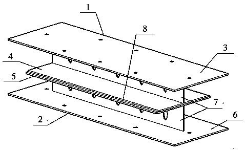
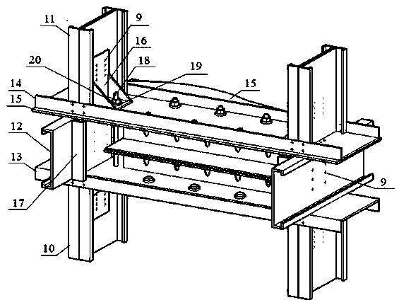
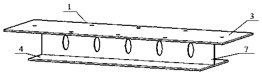
[0037] Comprising beams, trusses, and floor panels that cooperate with each other:

[0038] In order to improve the bearing capacity of the column, the column is composed of two C-shaped steels that are closely attached back to back and fixed with self-tapping screws 9, including the lower column 10 and the upper column 11;

[0039] The beam includes a C-shaped steel floor beam 12, a U-shaped steel roof beam 13 of the lower house with downward openings connecting two adjacent columns and a U-shaped steel bottom beam 14 of the upper house with an upward opening;

[0040] The floor structure board 15 is made of galvanized steel sheet on the bottom layer and bamboo plywood on the upper layer through glue, and there are bolt holes on it;

[0041] and:

[0042] There is an anti-extraction element 16 composed of a bottom plate, a back plate and a side plate. The bottom plate is provided with bolt holes and the back plate is provided with self-tapping screw holes.

[0043] C-shaped...


PUM


Abstract

The invention provides a reinforced part between wall layers in a cold-formed thin-walled steel house. The reinforced part between the wall layers in the cold-formed thin-walled steel house is characterized in that the reinforced part comprises upper H-shaped steel (1) and a lower H-shaped steel (2), wherein the upper H-shaped steel (1) comprises an upper steel upper wing edge (3), an upper steel lower wing edge (4) and webs (7), and the lower H-shaped steel (2) comprises a lower steel upper wing edge (5), a lower steel lower wing edge (6) and webs (7); part of the upper steel lower wing edge (4) and the webs (7) is cut by the upper H-shaped steel (1) in accordance with the equal proportion and along the periphery, part of the lower steel upper wing edge (5) and the webs (7) is cut by the lower H-shaped steel (2) in accordance with the equal proportion and along periphery, and the part cut by the upper H-shaped steel (1) is equal to the part cut by the lower H-shaped steel (2); and after the parts are cut, the upper steel lower wing edge (4) and the lower steel upper wing edge (5) are welded together to form an H-shaped steel laminated combined reinforced part, and bolt holes which penetrate through the upper steel upper wing edge (3) and the lower steel lower wing edge (6) are formed in the two ends of the H-shaped steel laminated combined reinforced part.

Description

1. Technical field [0001] The invention relates to a prefabricated multi-layer cold-formed thin-walled steel house inner wall interlayer reinforcing component, which is especially suitable for installation in low-rise and multi-layered layered-assembled cold-formed thin-walled steel structure houses, belonging to the technical field of construction engineering . 2. Background technology [0002] The load-bearing composite wall of the cold-formed thin-walled steel house is usually composed of cold-formed thin-walled steel wall frame columns, filled with thermal insulation cotton and covered with gypsum board, etc. It is easy to realize resource recycling and reuse; the wallboard has good thermal insulation performance , reduce the energy consumption in the process of use, and meet the national green environmental protection requirements; the main parts such as wall frame columns, floor beams, wall panels, etc. are processed in the factory and transported to the site for assem...

Claims


Application Information

Patent Timeline
Patent Type & Authority Patents(China)
IPC IPC(8): E04B2/58E04B1/24
CPCE04B1/24E04B2/58
Inventor 褚云朋姚勇贾彬陈俊颖甘璐陈晓强张兆强邓勇军
Owner SOUTHWEAT UNIV OF SCI & TECH
Why Eureka
Try Eureka