
Engine system and automobile applying engine system

A technology for engine systems and turbines, applied to engine components, combustion engines, machines/engines, etc., can solve the problems that the exhaust gas recirculation system cannot be accurately controlled, the multi-stage turbocharging system cannot be adjusted, and the cost of the engine system is high

Active Publication Date: 2017-05-31
QOROS
View PDF39 Cites 0 Cited by
  • Summary
  • Abstract
  • Description
  • Claims
  • Application Information

AI Technical Summary

Problems solved by technology

[0006] The technical problem to be solved by the present invention is to overcome the problem in the prior art that the opening and closing of the air valve of each cylinder cannot be individually controlled in the traditional engine, the cost of the engine system is relatively high, and the multi-stage turbocharging system cannot be adjusted and exhaust gas recirculation The defect that the system cannot be precisely controlled provides an engine system and an automobile using the engine system

Method used


Image

  • Engine system and automobile applying engine system
  • Engine system and automobile applying engine system
  • Engine system and automobile applying engine system

Examples


Embodiment Construction

[0147] Various embodiments of the present invention will be described with reference to the drawings. In the specification and drawings, elements with similar structures or functions will be represented by the same element symbols. It can be understood that the drawings are only for reference and explanation, and are not used to limit the present invention. The dimensions shown in the drawings are only for the convenience of clear description, and do not limit the proportional relationship or provide an exhaustive description of the present invention, nor do they limit the scope of the present invention.

[0148] In the description of the present invention, the terms "upper", "lower", "front", "rear", "left", "right", "vertical", "horizontal", "top", "bottom", " The orientation or positional relationship indicated by "inner" and "outer" is based on the orientation or positional relationship shown in the drawings, and is only for the convenience of describing the present inventio...


PUM


Abstract

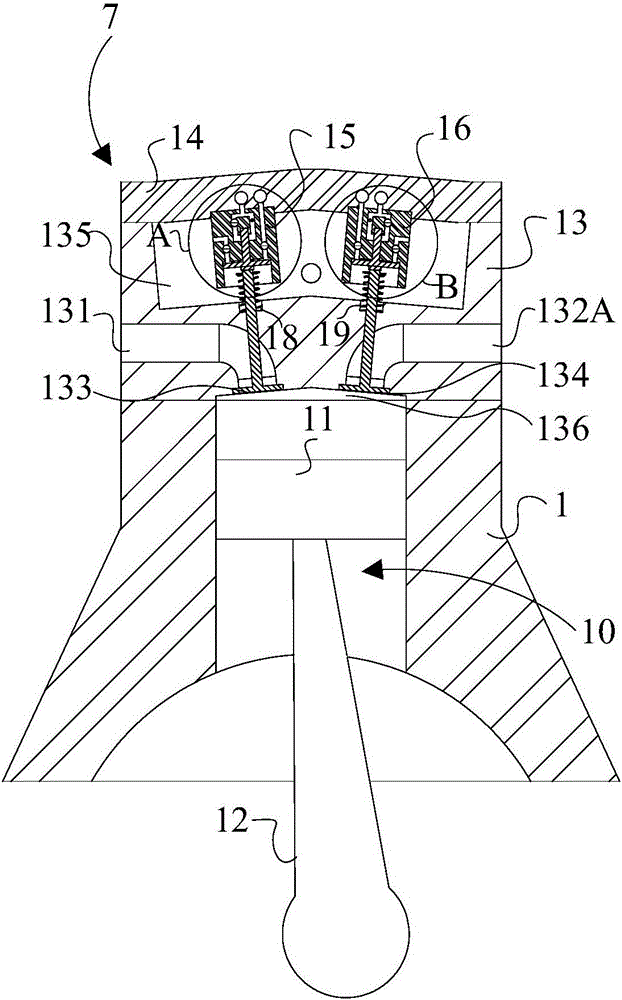
The invention discloses an engine system and an automobile applying the engine system. The engine system comprises an air cylinder body, an air cylinder cover, air valve executers, a first turbocharger and a second turbocharger. Combustion chambers each provided with a set of air inlets and a set of exhaust ports are formed by the air cylinder body and the air cylinder cover. Each set of air inlets comprise air inlets with air inlet valves. Each set of exhaust ports comprise the first exhaust port with a first exhaust valve and the second exhaust port with a second exhaust valve. Each air valve executer is set to independently control the corresponding air inlet valve or the corresponding first exhaust valve or the corresponding second exhaust valve. The first exhaust ports are connected with an air inlet of a first turbine, and the second exhaust ports are connected with an air inlet of a second turbine. According to the engine system and the automobile applying the engine system, the opening and closing time of the exhaust valves and the air inlet valves can be independently and accurately controlled so that the engine system and the automobile applying the engine system can adapt to different work conditions, the content of waste gas exhausted out of the air cylinder body and then circulating into the air cylinder body and the proportion of waste gas passing the first turbocharger and the second turbocharger can be controlled.

Description

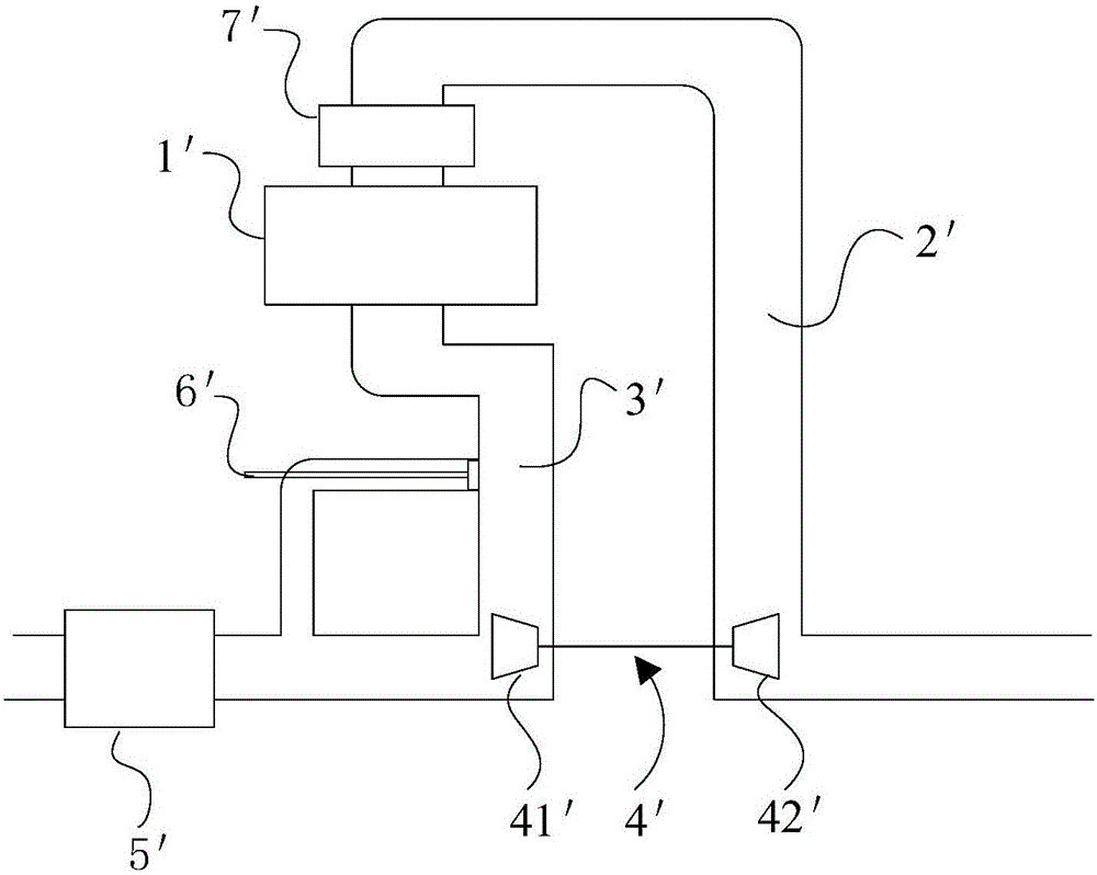
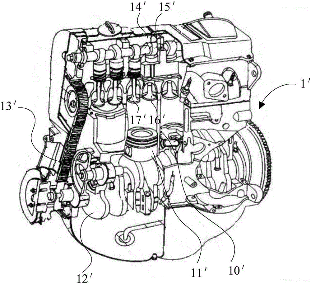
Technical field [0001] The invention relates to a power plant, in particular to an engine system and an automobile driven by the engine system. Background technique [0002] With the development of the automobile industry, automobiles have gained popularity all over the world. Among them, turbocharging technology has been increasingly used in engines. figure 1 Shows the system structure of a conventional turbocharged engine (internal combustion engine) system in the prior art, which includes an engine 1', an intake mechanism 2'for introducing air, an exhaust mechanism 3'for discharging exhaust gas, a turbine Supercharger 4'and catalytic converter 5'. The turbocharger 4'includes a turbine 41' and a compressor 42'. The compressor 42' is coaxially connected with the turbine 41'. The turbine 41' and the catalyst 5'are sequentially arranged in the exhaust mechanism 3', so that the exhaust gas generated by the engine 1'first passes through the turbine 41' and then enters the catalys...

Claims


Application Information

Patent Timeline
Patent Type & Authority Applications(China)
IPC IPC(8): F02B75/20F02B37/013F01L9/02F01L1/26F01N3/10F01N13/10F01L9/10
CPCF01L1/267F01N3/10F01N13/107F02B37/013F02B75/20F02B2075/1816F01L9/10Y02A50/20Y02T10/12
Inventor 李红雨马克·穆萨马里奥·伊凡尼欣韩昌虎克劳斯·施密特王华阳孙建国廖亮
Owner QOROS
Learn More