Direct-expansion type solar heat and electricity co-generation system provided with two stages of heat storage water tanks

A combined heat and power supply and hot water tank technology, which is applied in solar thermal power generation, mechanical power generated by solar energy, energy industry, etc., can solve the problems of high technical difficulty, poor independence of power generation and heat supply, and high cost, and avoid two Second heat exchange, easy access, low cost effect

Active Publication Date: 2017-05-31
UNIV OF SCI & TECH OF CHINA
View PDF18 Cites 8 Cited by
  • Summary
  • Abstract
  • Description
  • Claims
  • Application Information

AI Technical Summary

Problems solved by technology

[0009]In order to solve the difficulty and high cost of high-temperature heat storage and high-temperature heat collection technology in traditional solar thermal power generation systems based on turbo expanders (steam turbines), and the traditional solar thermal power In order to solve the problems of poor independence of power generation and heat supply in the cogeneration system, the present invention provides a direct expansion solar heat and power cogeneration system with two-stage hot water storage tanks

Method used


Image

  • Direct-expansion type solar heat and electricity co-generation system provided with two stages of heat storage water tanks
  • Direct-expansion type solar heat and electricity co-generation system provided with two stages of heat storage water tanks
  • Direct-expansion type solar heat and electricity co-generation system provided with two stages of heat storage water tanks

Examples


Embodiment 1

[0077] Embodiment 1 works in mode 1: the system needs to generate power at full power, but does not need external heat supply.

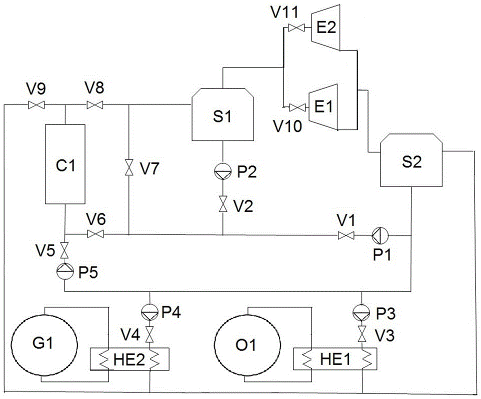
[0078] see figure 2 , the first outlet of the high-temperature water storage tank S1 is connected to the inlet of a screw expander E1 through a valve (only a single steam screw expander works).

[0079] In this mode 1, the first valve V1, the third valve V3, the sixth valve V6, the eighth valve V8 and the tenth valve V10 are opened, and the other valves are closed. The first water pump P1 and the third water pump P3 operate, and the other water pumps are turned off. Both a steam Rankine cycle at the top and an organic Rankine cycle at the bottom connected to the first heat exchanger HE1 are in operation. The water is heated and evaporated in the heat collector array C1, and enters the steam screw expansion unit E1 after passing through the high-temperature heat storage tank S1, and outputs work during the enthalpy drop process. The water vapor at...

Embodiment 2

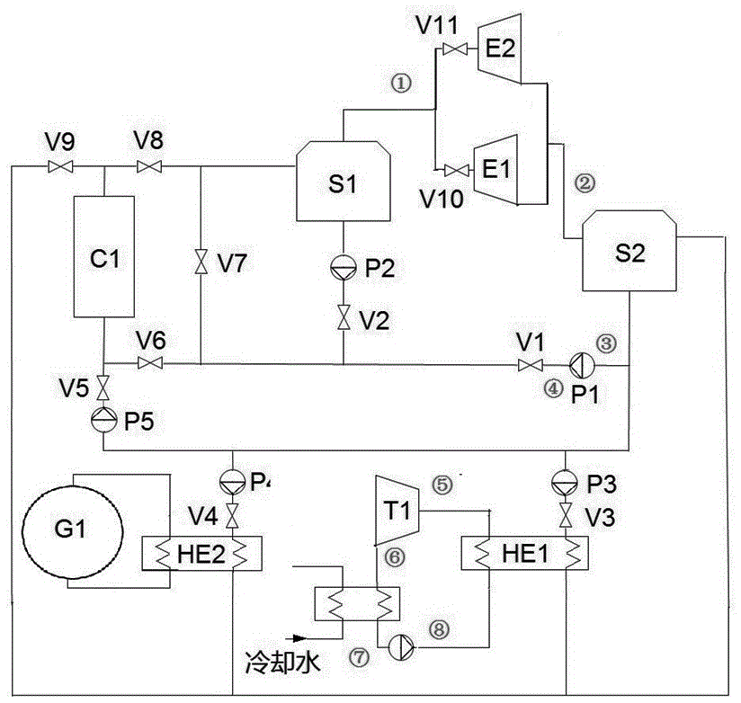
[0101] Embodiment 2 works in mode 2, that is, the system needs to generate power at full power, and at the same time needs to supply external heat. see figure 2, Compared with Example 1, Example 2 adds a screw expander E2, and the generating power is the same as that of the screw expander E1, which is 596kW. Collector array area from 8333m 2 increased to 13020 m 2 . The power of the ORC expander remains unchanged. The heating power of the heating system G1 is 2000kW.

[0102] In this mode 2, the first valve V1 , the third valve V3 , the fourth valve V4 , the sixth valve V6 , the eighth valve V8 , the tenth valve V10 and the eleventh valve V11 are opened, and the other valves are closed. The first water pump P1, the third water pump P3 and the fourth water pump P4 operate, and the other water pumps are turned off. While generating electricity at full power, the system provides heat to users through the fourth water pump and the second heat exchanger HE2.

[0103] Using ...

Embodiment 3

[0107] Embodiment 3 works under mode 7, that is, the system does not need to generate electricity, and does not need to supply heat.

[0108] In mode 7, the fifth valve V5 and the ninth valve V9 are opened, and the other valves are closed. The fifth water pump P5 runs, and the other water pumps are turned off. The heat obtained by the collector array C1 is stored in the low temperature storage tank S2.

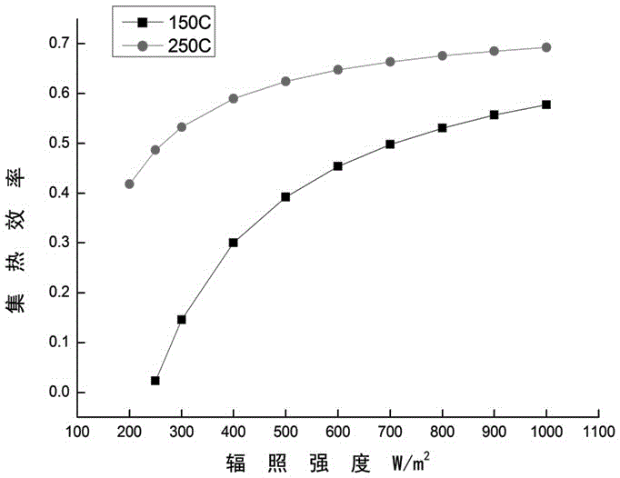
[0109] Take a type installed in the United States with a collector area of ​​2700 m 2 Taking the trough parabolic collector as an example, the optical efficiency of the collector is 0.762, and the first heat loss coefficient is 0.2521W / (m 2 K), the second heat loss coefficient is 0.002672W / (m 2 K 2 ). When the working temperature is 250°C (corresponding to high-temperature storage tank S1) and 150°C (low-temperature storage tank S2), the change of collector efficiency with radiation intensity is as follows: image 3 shown.

[0110] image 3 It shows that the heat colle...


PUM


Abstract

The invention relates to a direct-expansion type solar heat and electricity co-generation system provided with two stages of heat storage water tanks. The direct-expansion type solar heat and electricity co-generation system comprises a collector array, a high temperature stage heat storage water tank, a low temperature stage heat storage water tank, a screw expander unit, a first heat exchanger and a second heat exchanger; heat energy of the high temperature stage heat storage water tank is suitable for conversion of heat into power; the heat energy of the low temperature stage heat storage water tank can be further converted to electric energy through an organic Rankine cycle, and can also be directly supplied to a user; and the collector array transfers the heat energy to the high temperature stage heat storage water tank or the low temperature stage heat storage water tank according to the solar irradiation intensity or is used for generating steam. During power generation, a water working medium directly absorbs heat and expands in the collector array without overheating measure, the conversion of heat into power can still be carried out efficiently on a 200-300 DEG C middle temperature condition, and the power generation efficiency is 10-25%. According to the direct-expansion type solar co-generation system, the power generation stability of the system and an annual utilization ratio of equipment are improved and raised, the independence and flexibility of power generation and heat supply of the system are improved, the system control is simple, and a solar resource is utilized fully and efficiently.

Description

technical field [0001] The invention belongs to the technical field of solar thermal power generation, and in particular relates to a medium-low temperature direct expansion solar heat and power cogeneration system based on a screw expander. Background technique [0002] Direct expansion system (DSG) is an important way to reduce the cost of solar power generation in the future. In direct expansion systems, water vapor expands directly in the collector array, thus avoiding secondary heat transfer fluids such as heat transfer oil. The power consumption of the circulating pump in the heat collecting part will also be reduced. The constant temperature and high heat transfer coefficient of water vapor in the two-phase region are very beneficial to the operation of the collector. The European Union-funded Direct Expansion Solar Steam (DISS) project, which has operated for more than 6,000 hours, can demonstrate the viability of Direct Expansion technology. The 8 MWh demonstrati...

Claims


Application Information

Patent Timeline
Patent Type & Authority Applications(China)
IPC IPC(8): F03G6/06F01K23/02
CPCF01K23/02F03G6/06Y02E10/46Y02P80/15
Inventor 李晶裴刚高广涛王其梁季杰
Owner UNIV OF SCI & TECH OF CHINA
Why Eureka
Try Eureka