Gear case output shaft coupling for 100% low floor vehicle and transmission method of gear case output shaft coupling

A low-floor vehicle and gear box technology, applied in the transmission system, axles, wheels and other directions of locomotives, can solve the problems of increasing the intermediate links of torque transmission, large installation space requirements, and increasing size space, etc., to achieve efficient transmission and reduce installation. Space requirements, effect of reducing axial dimensions

Active Publication Date: 2017-05-31
株洲九方装备驱动技术有限公司 +1
View PDF4 Cites 4 Cited by
  • Summary
  • Abstract
  • Description
  • Claims
  • Application Information

AI Technical Summary

Problems solved by technology

[0007] All disclosed in the above-mentioned patent documents are couplings for low-floor vehicles, but the above-mentioned couplings for low-floor vehicles have many components, thereby increasing the overall size space, so the above-mentioned coup

Method used


Image

  • Gear case output shaft coupling for 100% low floor vehicle and transmission method of gear case output shaft coupling
  • Gear case output shaft coupling for 100% low floor vehicle and transmission method of gear case output shaft coupling
  • Gear case output shaft coupling for 100% low floor vehicle and transmission method of gear case output shaft coupling

Examples


Embodiment 1

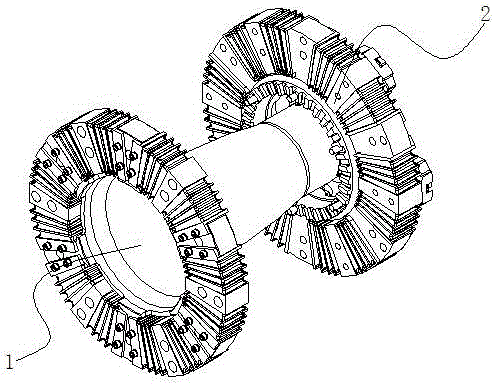
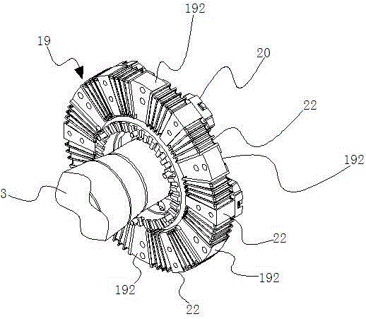
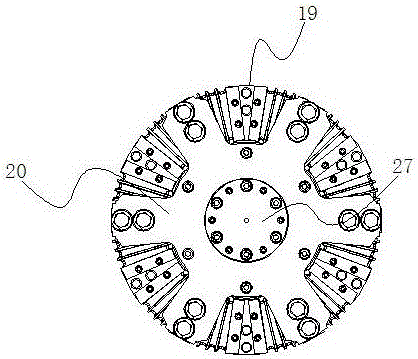
[0046] Embodiment 1: as Figure 1 to Figure 5 As shown, a 100% low-floor vehicle gearbox output coupling includes a transmission hollow shaft 1 and a gearbox transmission part 2, and the transmission hollow shaft 1 includes a hollow shaft 3 and a wheel drive disc arranged on one end of the hollow shaft 3 4. The transmission part 2 of the gearbox is connected to the other end of the hollow shaft 3, and the output shaft 5 of the gearbox is connected to the transmission part 2 of the gearbox. The hollow shaft 3 is in the shape of a hollow truncated cone. 3 on the side of the big end; the wheel 7 with the axle 6 is connected to the wheel drive disc 4, when the wheel 7 is connected to the wheel drive disc 4, the protruding part 711 on the outer side of the wheel is located in the big end of the hollow shaft 3 cavity. The applicant found in actual work that when the transmission hollow shaft is installed on the wheel, the protruding parts on the outside of the wheel will also affec...

Embodiment 2

[0063] Embodiment 2: as Figure 18 and Figure 19 As shown, compared with Embodiment 1, the difference is that the hollow shaft 3 is arranged in multiple sections along the axial direction of the hollow shaft 3 , and the outer peripheral surfaces of the multi-section hollow shaft 3 are arranged in sequence in a state of alternating straight surfaces 31 and inclined surfaces 32 . In this embodiment, the structure of the hollow shaft is further improved. The hollow shaft is arranged in a multi-section structure, and the outer diameter of the hollow shaft is gradually divided into sections from the big end of the hollow shaft to the small end of the hollow shaft along the axial direction of the hollow shaft. Reduced, this nonlinear structure can make the strength of the hollow shaft higher.

[0064] In this embodiment, the hollow shaft is arranged in five sections along the axial direction of the hollow shaft, including segmented hollow shaft one D1, segmented hollow shaft two D...


PUM


Abstract

The invention discloses a gear case output shaft coupling for a 100% low floor vehicle and a transmission method of the gear case output shaft coupling. The gear case output shaft coupling for the 100% low floor vehicle comprises a transmission hollow shaft and a gear case transmission part; the transmission hollow shaft comprises a hollow shaft body and a wheel transmission disk arranged at one end of the hollow shaft body; the gear case transmission part is connected with the other end of the hollow shaft body; a gear case output shaft is connected with the gear case transmission part; the hollow shaft body is in the shape of a hollow cone frustum; the wheel transmission disk is arranged on one side located at the large head end of the hollow shaft body; wheels are connected to the wheel transmission disk; and when the wheels are connected with the wheel transmission disk, a protruding part on the outer side portion of each wheel is located in an inner cavity of the large head end of the hollow shaft body. According to the gear case output shaft coupling for the 100% low floor vehicle and the transmission method of the gear case output shaft coupling, on the premise that the transmission performance is guaranteed, the installing space requirement of the whole gear case output shaft coupling can be lowered, the gear case output shaft coupling is suitable for a narrow and small installing space of the low floor vehicle, the intermediate links during torque transmission can also be reduced, and the fault rate is lowered.

Description

technical field [0001] The invention relates to a coupling and a transmission method thereof, in particular to an output coupling of a gearbox for a 100% low-floor vehicle and a transmission method thereof. Background technique [0002] 100% low-floor modern trams adopt cutting-edge technologies such as bow-less current collection and super capacitors. The floor is only 35 cm from the rail surface, and no platforms are required. The maximum transport capacity is 6 to 8 times that of buses. The vehicle can adopt battery and super capacitor parallel hybrid power, provide a full-line non-catenary solution, strong climbing ability, the minimum turning radius is only 19 meters, and the existing roads in the city can be laid. It is green, environmentally friendly, and low noise. It is the most advanced in the world One of the urban transportation systems. [0003] The gearbox output coupling is an elastic coupling, which is an important part of the power transmission system of 10...

Claims


Application Information

Patent Timeline
IPC IPC(8): F16D3/64B60B35/14B60B35/00B61C9/00
CPCB60B35/002B60B35/14B61C9/00F16D3/64F16D3/68
Inventor 王力军姜宇飞
Owner 株洲九方装备驱动技术有限公司
Why Eureka
Try Eureka