
Composite connector for high-speed motor vehicle anti-yaw damper system

A shock absorber and composite technology, applied in the direction of shock absorbers, shock absorbers, motor vehicles, etc., can solve problems such as high joint stiffness, inability to meet the high elasticity requirements of anti-snaking shock absorbers, and rubber damage, etc., to achieve The cost is controllable, the large-scale application prospect is highlighted, and the structure is simple

Active Publication Date: 2017-05-31
深圳市中车业成实业有限公司
View PDF7 Cites 1 Cited by
  • Summary
  • Abstract
  • Description
  • Claims
  • Application Information

AI Technical Summary

Problems solved by technology

However, the anti-snaking damper requires the joint to have high rigidity, and at the same time it is required to have a certain degree of elasticity, so as to block the high-frequency vibration it endures during operation. The above-mentioned ball joint bearing cannot meet the high elasticity requirement of the anti-snaking damper.
Therefore, in the anti-snaking shock absorber, the rigidity of the joint is required to be high. For example, a high-speed rail vehicle requires the joint stiffness to be 70 KN / mm, that is, the deformation of the small joint is only 1 mm when it is subjected to a force of 7 tons. In terms of area, the rubber can only be made very "hard", but such joints also have to withstand more than 10° of torsion and swing. Cause damage to the rubber or disengage from the vulcanized rubber parts; in addition, the large bending moment generated on the shock absorber body increases the force between the piston and the working cylinder in the shock absorber and increases the wear
In short, the radial stiffness of the joint of the anti-snaking shock absorber should be large—the rubber should be “hard” and easy to rotate—“soft”, the contradiction between the two makes the manufacturer at a loss

Method used

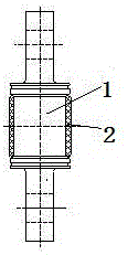
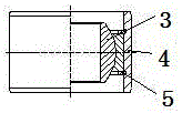
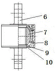

Image

  • Composite connector for high-speed motor vehicle anti-yaw damper system
  • Composite connector for high-speed motor vehicle anti-yaw damper system
  • Composite connector for high-speed motor vehicle anti-yaw damper system

Examples


Embodiment Construction

[0020] In order to enable those skilled in the art to better understand the technical solutions of the present invention, the present invention will be further described in detail below in conjunction with specific examples. The embodiments described below are exemplary only for explaining the present invention and should not be construed as limiting the present invention.

[0021] The composite joint for the anti-snaking shock absorber provided by the present invention, when the joint is subjected to the axial load of the shock absorber, the rigidity of the ball bearing is extremely high, and after the rubber is pressed into the ball bearing, the series rigidity of the two meets the rigidity of the joint of the vehicle Requirements: When the mounting rod twists or swings relative to the shock absorber, the ball head of the ball bearing slides relative to the ball bowl. Due to the extremely small resistance moment, the rotation has minimal impact on the rubber layer and the sho...


PUM


Abstract

Aiming at problems existing in the prior art, the invention provides a composite connector for a high-speed motor vehicle anti-yaw damper system. The provided composite connector for the high-speed motor vehicle anti-yaw damper system comprises a component A and a component B. The component A comprises an installation rod and a tubular rubber layer. The component B comprises a ball joint bearing, a circlip for hole and an outer ring. The tubular rubber layer of the component A and the ball joint bearing of the component B are in series connection and are fixed in the outer ring of the component B. Therefore, when the connector is subjected to the axial load of a damper, the rigidity of a ball bearing is very high, and after rubber is pressed into the ball bearing, the series connection rigidity of the rubber and the ball bearing meets the rigidity requirement of a vehicle for the damper. When the installation rod turns or swings relative to the damper, a ball head of the ball bearing and a ball bowl slide and rotate relatively, and due to the fact that resisting moment is very small, the influence of rotation on the rubber layer and a damper body is very small. In addition, the composite connector is simple in structure and controllable in cost and has outstanding scale application prospects.

Description

technical field [0001] The invention belongs to the field of high-speed rail vehicles, and in particular relates to a composite joint for anti-snaking shock absorbers of high-speed trains. Background technique [0002] In the prior art, in the general shock absorber, since the joint stiffness is required to be small and the rubber in the joint is relatively soft, the torsion and swing of the rubber joint can easily deform the rubber layer in the joint tangentially without damage; The bending moment generated by the shock absorber body is also small, which has little influence on the work of the shock absorber. In order to avoid misalignment of both ends of the hydraulic shock absorber and changes in the relative positions of the two ends during work, rubber joints with relatively small stiffness are generally installed at both ends of the shock absorber, which not only allow the end installation parts to be fixed relative to the shock absorber The torsion and swing at an an...

Claims


Application Information

Patent Timeline
IPC IPC(8): F16F9/54F16C11/06F16C11/08
CPCF16C11/0609F16C11/0666F16C11/0685F16C11/0695F16C11/083F16C2208/10F16C2226/12F16C2326/05F16C2326/10F16F9/54
Inventor 吕再昌吴旭
Owner 深圳市中车业成实业有限公司
Learn More