Coanda-effect-based air-conditioned plant roof air-film cooling apparatus

A technology of Coanda effect and cooling device is applied in the field of air-film cooling device on the roof of air-conditioning workshop, which can solve the problems of high cost, poor cooling effect, troublesome daily cleaning and maintenance, etc. The effect of request reduction

Active Publication Date: 2017-05-31
NANHUA UNIV
View PDF5 Cites 0 Cited by
  • Summary
  • Abstract
  • Description
  • Claims
  • Application Information

AI Technical Summary

Problems solved by technology

It solves the problems of high cost, troublesome daily cleaning and maintenance, and poor cooling effect of existing factory roof cooling methods (and devices)

Method used


Image

  • Coanda-effect-based air-conditioned plant roof air-film cooling apparatus
  • Coanda-effect-based air-conditioned plant roof air-film cooling apparatus
  • Coanda-effect-based air-conditioned plant roof air-film cooling apparatus

Examples


Embodiment 1

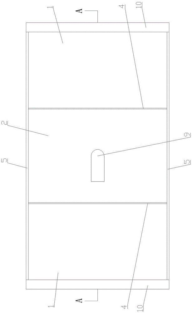
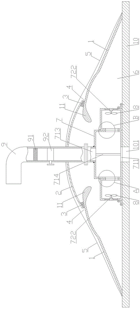
[0038] Such as Figure 1-4 As shown, the air-film cooling device on the roof of an air-conditioning factory based on the Coanda effect includes a Coanda airfoil 1, an arc-shaped upper cover 2, a connecting block 3, an end plate 5, an air box 7, an exhaust fan 8, a fresh air pipe 9 and Bottom plate 10 .

[0039] The Coanda airfoil 1 is located above the bottom plate 10 and below the side of the arc-shaped upper cover 2 , and an arc-shaped diversion head 11 is provided at one end thereof. The smooth curved surface of the arc-shaped flow guide head 11 can reduce turbulent flow noise caused by the airflow encountering sharp objects. There are two Coanda airfoils 1 , which are respectively located under the two sides of the arc-shaped upper cover 2 . The outer surface of the Coanda airfoil 1 is a Coanda curved surface.

[0040] The arc-shaped upper cover 2 is arranged on the upper end of the Coanda airfoil 1, and it is connected to the arc-shaped guide head 11 of the Coanda airf...

Embodiment 2

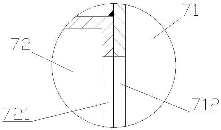
[0050] Such as Figure 6-7 As shown, the only difference between this embodiment and embodiment 1 is that the number of Coanda airfoil 1 is one. There are four end plates 5 , two of which are connected to both sides of the Coanda airfoil 1 and the arc-shaped upper cover 2 , and the other two are connected to the arc-shaped upper cover 2 . The static pressure chamber 71 is only provided with an air outlet A712 on one side wall.

[0051] Briefly describe the use of the present invention: as Figure 5 , 8 As shown, before use, the hole 991 connected to the room needs to be opened in advance on the roof 99 of the factory building. During use, the present invention is placed on the roof 99 of the factory building. The exhaust fan 8, the cold air in the room enters the static pressure chamber 71 through the hole 991 on the roof 99 of the factory building, the air hole 101 on the bottom plate 10 and the air inlet A711 of the static pressure chamber 71, and then passes through the ...


PUM


Abstract

A Coanda-effect-based air-conditioned plant roof air-film cooling apparatus comprises Coanda wing plates, an arc upper cover, connection blocks, end plates, an air box, a draught fan and a bottom plate; the Coanda wing plates are arranged above the bottom plate below the lateral edges of the arc upper cover, one end of each Coanda wing plate is provided with an arc guide head, the arc upper cover is connected with the arc guide heads through the connection blocks, a special-shaped air outlet is arranged between the arc upper cover and each Coanda wing plate, the Coanda wing plates, the arc upper cover, the end plates and the bottom plate form an air outlet cavity, the air box is mounted on the bottom plate, a static cavity and a draught cavity are arranged in the air box, the draught fan is mounted in the draught cavity, and the bottom plate is provided with an air hole communicated with the static cavity. Exhausted air from an air-conditioned plant is supplied out of narrow slits of a Coanda-effect-based air guidance unit and flows along Coanda surface, the air around the roof is guided under low volume, air film is finally formed on the outer surface of the roof, the air film attaches to a wall at high speed, heat may be brought away sufficiently, and the temperature of the outer surface of the roof is reduced.

Description

technical field [0001] The invention relates to a roof cooling device, in particular to a roof air film cooling device based on the Coanda effect. Background technique [0002] With the rapid development of industry, a large number of factory buildings have emerged as the times require, and correspondingly, the energy consumption of air conditioners has also increased significantly. According to statistics, the air-conditioning energy consumption of factories accounts for about 30%-60% of building energy consumption. Therefore, it is becoming more and more important to develop green energy buildings and reduce air-conditioning energy consumption. [0003] Most of the roofs of air-conditioning factories are steel plate structures, which have poor thermal insulation performance and high heat transfer coefficient. During the daytime in summer, the temperature of the outer surface of the factory building varies with the time. The lowest temperature is 40°C, the highest temperat...

Claims


Application Information

Patent Timeline
Patent Type & Authority Applications(China)
IPC IPC(8): F24F5/00F24F9/00F24F13/24F24F13/26E04D13/17
CPCF24F5/0003F24F9/00F24F13/24F24F13/26E04D13/17F24F2013/247
Inventor 彭小勇张园胡畏叶雅玲
Owner NANHUA UNIV
Why Eureka
Try Eureka