Tunnel type multi-stage heat pump series drying and dehumidifying system

A drying and dehumidification, tunnel-type technology, applied in the field of tunnel-type multi-stage series heat pump drying and dehumidification systems, can solve the problems of large temperature difference between supply and return air, frosting of evaporators, and low heat pump performance, so as to increase the supply air temperature and improve drying. Efficiency, the effect of improving utilization

Inactive Publication Date: 2017-05-31
TECHNICAL INST OF PHYSICS & CHEMISTRY - CHINESE ACAD OF SCI
View PDF3 Cites 12 Cited by
  • Summary
  • Abstract
  • Description
  • Claims
  • Application Information

AI Technical Summary

Problems solved by technology

In areas where the outdoor environment is low, the fully open system and the semi-open system may easily cause the problem of frosting on the evaporator, resulting in low performance of the heat pump, or even malfunctioning, which seriously hinders the promotion of heat pumps in cold areas application
When the temperature difference between supply and return is large, it is difficult for the s

Method used


Image

  • Tunnel type multi-stage heat pump series drying and dehumidifying system

Examples


Example Embodiment

[0041] Embodiment 1 A tunnel-type multi-stage heat pump series drying and dehumidification system

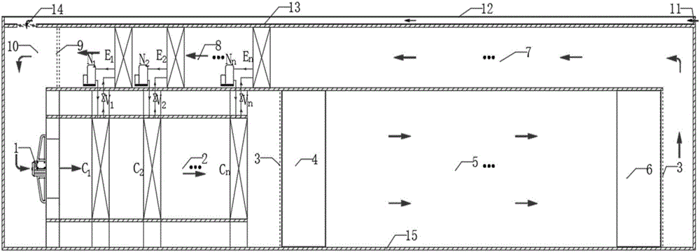
[0042] A tunnel-type multi-stage heat pump series drying and dehumidification system, such as figure 1 As shown, it includes: multi-stage heating chamber 2, multi-stage dehumidification chamber 8, tunnel drying chamber 5, return air duct 7 and mixing chamber 10;

[0043] The entrance of the multi-stage heating chamber 2 is provided with a main blower 1, and communicates with the mixing chamber 10; The perforated plate 3 is respectively arranged at the rear part, and the front door 4 of the tunnel drying chamber and the back door 6 of the tunnel drying chamber are provided; the outlet of the tunnel drying chamber 5 is connected with the inlet of the multi-stage dehumidification chamber 8 through the return air duct 7; The outlet of the multi-stage dehumidification chamber 8 communicates with the mixing chamber 10, and a water baffle 9 is arranged between them. The multi-stage h...

Example Embodiment

[0046] Example 2 Method for drying materials in a tunnel-type multi-stage heat pump series drying and dehumidification system

[0047]Under the action of the main fan 1, the gas is heated and heated step by step from the first-stage condenser C1 to the n-stage condenser Cn, and the step-by-step heated gas enters the tunnel-type drying chamber 5 and is heated with fresh materials. Humidity transfer, the high-temperature and high-humidity gas passes through the return air duct 7 to carry out step-by-step cooling and dehumidification from the nth-stage evaporator En to the first-stage evaporator E1, and the air after step-by-step cooling and dehumidification enters the mixing chamber (10), Through the main fan 1, it enters again from the first-stage condenser C1 to the n-th-stage condenser Cn to complete the cycle;

[0048] Wherein, the fresh material is loaded on the side of the back door 6 of the tunnel drying chamber, and the material gradually moves along the opposite air sup...


PUM


Abstract

The invention discloses a tunnel type multi-stage heat pump series drying and dehumidifying system. The tunnel type multi-stage heat pump series drying and dehumidifying system comprises a multi-stage heating chamber, a multi-stage dehumidification chamber, a tunnel type drying chamber, a return opening and a mixing chamber. An inlet of the multi-stage heating chamber is provided with a main air blower and the multi-stage heating chamber is connected with the mixing chamber. An outlet of the multi-stage heating chamber is connected with an inlet of the tunnel type drying chamber. An outlet of the tunnel type drying chamber is connected with an inlet of the multi-stage dehumidification chamber through the return opening. An outlet of the multi-stage dehumidification chamber is connected with the mixing chamber. The closed multi-stage heat pump drying and dehumidification system of the invention is not affected by the external environment. Compared with a single-stage heat pump drying system, multi-stage dehumidification effectively removes the moisture in the dry air and reduces the temperature difference of the single-stage air, and multi-stage heating effectively improves the air supply temperature and reduces the temperature difference of single-stage air. The pressure ratio of a compressor is reduced. The efficiency of the compressor and the dehumidification efficiency are improved effectively.

Description

technical field [0001] The invention relates to the technical field of drying of agricultural by-products. More specifically, it relates to a tunnel type multi-stage series heat pump drying and dehumidification system. Background technique [0002] The application of heat pump technology in material drying has been studied by a large number of domestic and foreign literatures, and has been applied in actual processing and production practices in China. In areas where the outdoor environment is low, the fully open system and the semi-open system may easily cause the problem of frosting on the evaporator, resulting in low performance of the heat pump, or even malfunctioning, which seriously hinders the promotion of heat pumps in cold areas application. When the temperature difference between supply and return is large, it is difficult for the single-stage heat pump system to meet the requirements, resulting in an excessive pressure ratio. [0003] Therefore, it is necessary...

Claims


Application Information

Patent Timeline
IPC IPC(8): F26B15/00F26B23/00
CPCF26B15/00F26B23/005
Inventor 苑亚杨鲁伟张振涛魏娟杨俊玲张冲孙椰望陈嘉祥
Owner TECHNICAL INST OF PHYSICS & CHEMISTRY - CHINESE ACAD OF SCI
Why Eureka
Try Eureka