Heat exchange provided with sharp structure out of pipe

A technology of heat exchangers and heat exchange tube bundles, which is applied in the field of shell-and-tube heat exchangers and waste heat discharge heat exchangers. It can solve the problems of the decrease of heat transfer coefficient on the shell side and the inability to meet the requirements of waste heat discharge, so as to improve heat transfer. Effect, Realization of natural circulation capacity and heat carrying capacity, Effect of shortened path

Active Publication Date: 2017-05-31
NUCLEAR POWER INSTITUTE OF CHINA
View PDF7 Cites 31 Cited by
  • Summary
  • Abstract
  • Description
  • Claims
  • Application Information

AI Technical Summary

Problems solved by technology

[0003] Generally, a vapor-liquid two-phase flow will be formed in the shell side of the waste heat exchanger. Because of the existence of bubbles in the vapor-liquid two-phase flow, the heat transfer coefficient of the shell side will decrease, which cannot meet the normal waste heat discharge requirements.

Method used


Image

  • Heat exchange provided with sharp structure out of pipe
  • Heat exchange provided with sharp structure out of pipe
  • Heat exchange provided with sharp structure out of pipe

Examples


Embodiment Construction

[0036] The specific embodiments of the present invention will be described in detail below in conjunction with the accompanying drawings.

[0037] In this article, if there is no special explanation, when it comes to formulas, " / " means division, and "×" and "*" mean multiplication.

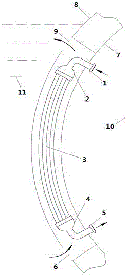
[0038] Such as figure 1 As shown, a heat exchanger includes a tube side and a shell side, and the tube side includes an inlet pipe 1, an inlet chamber 2, a heat transfer tube bundle 3, an outlet chamber 4 and an outlet pipe 5. The hot fluid enters the inlet chamber 2 from the inlet pipe 1, and passes through the heat transfer tube bundle 3, the outlet chamber 4 and the outlet pipe 5 in sequence; the shell side includes the inlet channel 6, the inner shell 7, the outer shell 8 and the outlet Channel 9, the cold fluid passes through the inlet channel 6, the space defined by the inner shell 7 and the outer shell 8, and the outlet channel 9, the inlet chamber 2, the heat transfer tube bundle 3, and ...


PUM


Abstract

The invention provides a heat exchanger. The heat exchanger comprises a pipe pass side and a shell pass side; the pipe pass side includes an inlet pipe, an inlet cavity, a heat transfer pipe bundle, an outlet cavity and an outlet pipe; a hot fluid enters the inlet cavity from the inlet pipe to pass through the heat transfer pipe bundle, the outlet cavity and the outlet pipe in sequence; the shell pass side includes an inlet channel, an inner shell, an outer shell and an outlet cavity; a cold fluid passes through space limited by the inlet channel, the inner shell and the outer shell and the outlet cavity in sequence; the inlet cavity, the heat transfer pipe bundle and the outlet cavity are arranged in space limited by the inner shell and the outer shell; a metal rod outwards extends from the outer wall of the heat transfer pipe bundle; the end part of the metal rod is a sharp structure; and the direction from the outer wall of the heat transfer pipe bundle to the end part of the metal rod is opposite to the flowing direction of the cold fluid. The rod with the sharp end part is arranged at the external of the heat exchange pipe; in flowing of a gas-liquid two-phase flow, on the one hand, the laminar flow bottom layer can be broken, and the heat transfer area is increased for forced heat transfer; because of the rod, the flowing resistance is low, and the shell pass flowing resistance cannot be increased; and as the sharp end part is provided, bubbles can be punctured to realize increment of a gas-liquid interface and a gas-phase boundary layer and reinforcement of the disturbance.

Description

technical field [0001] The invention belongs to the field of heat exchangers, and relates to a shell-and-tube heat exchanger, in particular to a waste heat discharge heat exchanger with low flow resistance, compactness, higher natural circulation capacity and safety. Background technique [0002] The waste heat removal heat exchanger is the heat exchange hub of the waste heat removal system, and is an important device related to various equipment, such as the safety of reactor shutdown in nuclear reactions. At present, the third-generation nuclear power technology and marine nuclear power plant generally adopt passive waste heat removal system to further improve the inherent safety, which requires the flow resistance of the waste heat discharge cooler to be as low as possible to improve the natural circulation flow. The waste heat exhaust cooler is required to be compact and small in order to save the stack layout space. Most of the existing waste heat removal coolers are a...

Claims


Application Information

Patent Timeline
Patent Type & Authority Applications(China)
IPC IPC(8): F28D1/047F28F9/00
CPCF28D1/047F28F9/00
Inventor 黄彦平徐建军周慧辉
Owner NUCLEAR POWER INSTITUTE OF CHINA
Why Eureka
Try Eureka