Smoke cooling device

A flue gas cooling device and flue gas technology, applied in the steam generation method using heat carrier, heat exchange equipment, fixed tubular conduit assembly, etc., can solve low operating efficiency, cracking of tube plate welds, and low heat exchange efficiency and other problems, to achieve the effect of prolonging the service life, improving the heat transfer coefficient and enhancing the heat transfer effect

Active Publication Date: 2017-05-31
JIANGNAN BOILERS & PRESSURE VESSELS ZHANGJIAGANG
View PDF8 Cites 4 Cited by
  • Summary
  • Abstract
  • Description
  • Claims
  • Application Information

AI Technical Summary

Problems solved by technology

At the same time, there are occasions with high pressure, occasions with stress cracking, or occasions with high temperature, or occasions where the content of combustibles is not too high. In the past, some users directly burned the tail gas or these high-temperature process gases with a torch, or directly It is discharged into the atmosphere, causing serious pollution to the environment. At present, some domestic industries also use flue gas coolers to recover heat, but there are many defects in the structure, such as cracking of tube plate welds, low heat transfer efficiency, and low operating efficiency. wait

Method used


Image

  • Smoke cooling device
  • Smoke cooling device
  • Smoke cooling device

Examples


Embodiment Construction

[0040] The technical solution of the present invention will be further described below in conjunction with the accompanying drawings.

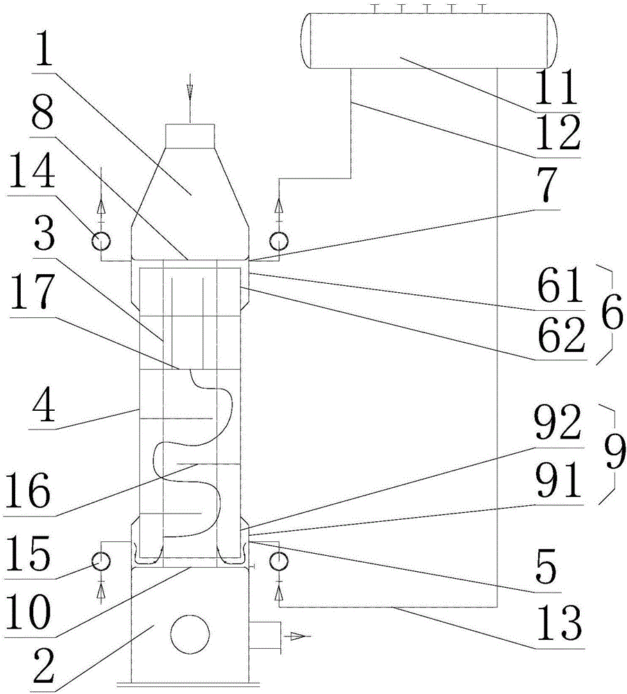
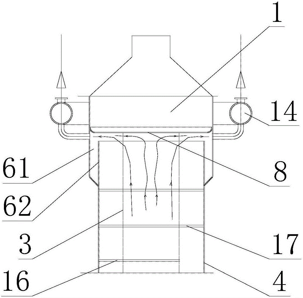
[0041] see Figure 1-4 As shown, the above-mentioned flue gas cooling device is used for heat exchange and cooling of high-temperature flue gas.

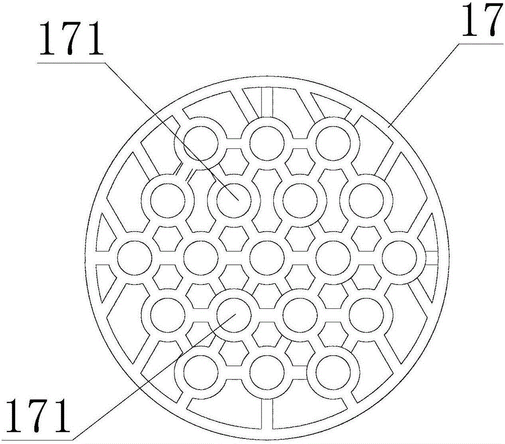
[0042] The flue gas cooling device includes an upper pipe box 1 for passing high-temperature flue gas, a lower pipe box 2 for passing out cooled flue gas, The heat exchange tubes 3 that enter and exit the flue gas; the heat exchange tubes 3 are distributed along the vertical direction.

[0043] The flue gas cooling device also includes a heat exchange mechanism for exchanging heat for the flue gas in the heat exchange tube 3, which is arranged between the upper tube box 1 and the lower tube box 2; The cylinder body 4 through which the water and the heat-exchanged water vapor pass out is also distributed along the vertical direction, and the heat exchange tube 3 is penetrated in the cylinder body 4...


PUM


Abstract

The invention discloses a smoke cooling device which comprises an upper pipe box used for leading in high-temperature smoke, a lower pipe box used for leading out cooled smoke, a heat exchange pipe used for communicating the upper pipe box and the lower pipe box and a heat exchange mechanism arranged between the upper pipe box and the lower pipe box. The heat exchange mechanism comprises a barrel used for leading in cooling water and leading out water steam obtained after heat exchange, a baffling mechanism arranged in the barrel, a water inlet arranged in the lower portion of the barrel and an upper portion speed increase cooling mechanism arranged at the upper portion of the barrel; the heat exchange pipe is arranged in the barrel in a penetrating manner; the upper portion speed increase cooling mechanism comprises an upper portion dilatation barrel arranged below the upper pipe box, an upper portion speed increase barrel arranged in the upper portion dilatation barrel in a penetrating manner and spaced with the upper portion dilatation barrel and a plurality of air outlets annularly formed in the periphery of the outer side of the upper portion dilatation barrel; and the lower end of the upper portion speed increase barrel is communicated with the upper end of the barrel, and the lower end of the upper portion dilatation barrel is fixedly arranged on the periphery of the outer side of the upper portion speed increase barrel. The smoke cooling device is high in heat exchange efficiency, high in safety factor and long in service life.

Description

technical field [0001] The invention relates to a flue gas cooling device. Background technique [0002] In some coal chemical industries or other industries, or subsequent processing industries, tail gas often needs to be treated. The process is treated by combustion to reduce the emission of combustibles, reduce the pollution to the atmosphere, and at the same time recover heat. There are many forms of flue gas cooling, but there are not many high-efficiency flue gas coolers that can operate. Tube sheet cracking is often encountered in engineering. The service life of flue gas coolers is generally five to ten years, and some are even shorter. Some even have leakage and tube sheet cracking problems during the start-up stage. [0003] The medium on the shell side of the flue gas cooler is usually water, which is used for heat exchange to generate steam, and the medium on the tube side is usually high-temperature and toxic materials. Once leaked, the damage will be very ser...

Claims


Application Information

Patent Timeline
Patent Type & Authority Applications(China)
IPC IPC(8): F28D7/16F28F9/24F22B1/18
CPCF22B1/18F28D7/16F28F9/24
Inventor 王宁张建东骆静霞黄建许春林王开朋
Owner JIANGNAN BOILERS & PRESSURE VESSELS ZHANGJIAGANG
Why Eureka
Try Eureka