Efficient and energy-saving sterile heat pipe energy recovery device

An energy recovery device and energy-saving technology, applied to indirect heat exchangers, lighting and heating equipment, etc., can solve the problems of inability to deal with welding points and dead angles, large consumption of chilled water, and large energy consumption, and achieve easy cleaning and Disassembly and assembly, good energy saving effect, and the effect of reducing consumption

Active Publication Date: 2017-05-31
QINGDAO UNIV
View PDF5 Cites 0 Cited by
  • Summary
  • Abstract
  • Description
  • Claims
  • Application Information

AI Technical Summary

Problems solved by technology

[0006] The purpose of the present invention is to overcome the shortcomings of the prior art, to propose and design a high-efficiency energy-saving aseptic heat pipe energy recovery device, to solve the problems of large energy consumption and frozen water consumption in ordinary high-temperature disinfection systems, and to solve the problems of ordinary casing type There are welding points and dead ends that cannot be dealt with in the heat exchanger, so as to avoid the possibility of cross-contamination when the solutions before and after sterilization flow on both sides of the heat exchange plate of the same heat exchanger

Method used


Image

  • Efficient and energy-saving sterile heat pipe energy recovery device
  • Efficient and energy-saving sterile heat pipe energy recovery device
  • Efficient and energy-saving sterile heat pipe energy recovery device

Examples


Embodiment 1

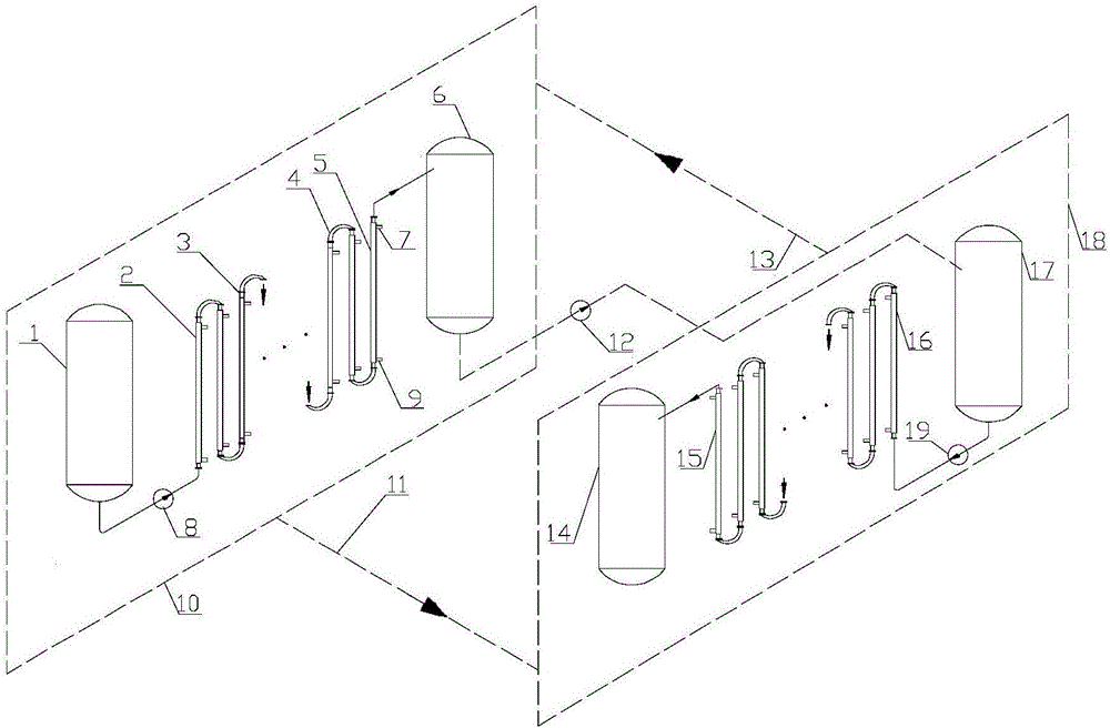
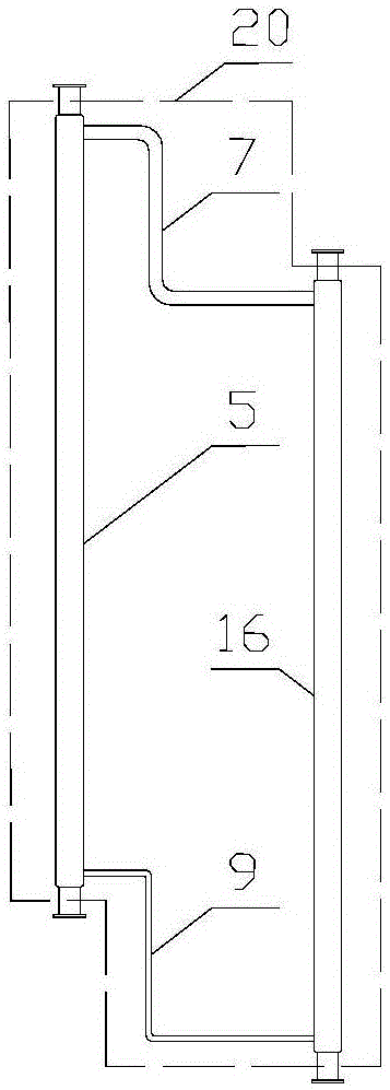
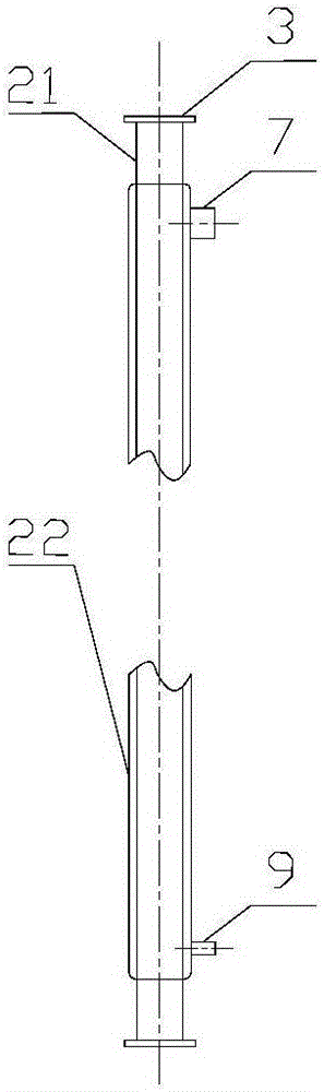
[0023] The high-efficiency and energy-saving aseptic heat pipe energy recovery device involved in this embodiment, the raw material container 1, the condensation section 2 of the last heat pipe subsystem, the clamp 3, the 180-degree elbow 4, and the condensation section 5 of the first heat pipe subsystem , heating tank 6, gas delivery pipe 7 of the heat pipe subsystem, cold solution pump 8, liquid return pipe of the heat pipe subsystem 9, cold solution flow subsystem before sterilization 10, liquid return pipe bundle 11 of the heat pipe subsystem, and transport pump 12. Air pipe bundle 13 of the heat pipe subsystem, cooling tank 14, evaporation section 15 of the last heat pipe system, evaporation section 16 of the first heat pipe system, standby heating tank 17, thermal solution pump 19, casing heat exchange The inner tube 21 of the device and the outer tube 22 of the sleeve heat exchanger are connected as a whole, and the number of condensing sections is 2 to 500, and the numb...

Embodiment 2

[0032] The main structure of the high-efficiency energy-saving aseptic heat pipe energy recovery device involved in this embodiment is the same as that described in Embodiment 1. When in use, the temperature of the hot solution in the standby heating tank 17 is controlled at 110°C, and the temperature of the cold solution in the raw material container 1 After passing through the energy recovery device of the present invention, the temperature of the hot solution is reduced from 110°C to 50°C, and the temperature of the cold solution is increased from 20°C to 80°C; on this basis, only Just heat 80°C to 110°C, which saves (80-20) / (110-20)=66.66% of the heating capacity, and at the same time in the cooling tank, only cools 50°C to 25°C, which saves (110-50) / (110-25)=70.59% cooling capacity; it can be seen that the energy-saving effect after the implementation of this embodiment is very significant, which can greatly reduce the operating cost of the production process, save costs a...


PUM


Abstract

The inventionbelongs to the technical field of energy and power engineering, and relates to an efficient and energy-saving sterile heat pipe energy recovery device. A raw material container, a condensation section of the last heat pipe subsystem, clamping hoops, 180-degree bends, a condensation section of the first heat pipe subsystem, a heating tank, gas conveying pipes of heat pipe subsystems, a cold solution pump, return liquid pipes of the heat pipe subsystems, an ante-sterilization cold solution flowing subsystem, a return liquid pipe bundle of the heat pipe subsystems, a conveying pump, a gas conveying pipe bundle of the heat pipe subsystems, a cooling tank, an evaporation section of the last heat pipe subsystem, an evaporation section of the first heat pipe subsystem, a standby heating tank, a hot solution pump, a double-pipe heat exchanger inner pipe and a double-pipe heat exchanger outer pipe are connected into a whole, and the device comprises the ante-sterilization cold solution flowing subsystem, a post-sterilization hot solution flowing subsystem and a heat pipe working medium circulating subsystem. The efficient and energy-saving sterile heat pipe energy recovery device is good in energy-saving effect, convenient to dismount and mount, capable of avoiding cross contamination, scientific and reasonable in structural design, convenient to apply and popularize, and good in application environment.

Description

[0001] Technical field: [0002] The invention belongs to the technical field of energy and power engineering, and relates to a high-efficiency and energy-saving aseptic heat pipe energy recovery device, in particular to an energy recovery system that applies the high-efficiency and energy-saving heat pipe technology to the industrial fields with aseptic requirements such as medicine and food. . [0003] Background technique: [0004] The pharmaceutical and food industries have high-temperature sterilization process requirements for certain products. This process generally involves heating products at room temperature to about 110°C with steam or electric energy, and keeping them warm for a period of time to complete the sterilization process. Finally, the sterilized product is cooled to room temperature with the frozen water provided by the refrigeration system, and then the next process is carried out; and this heating and cooling process consumes a lot of heat and cooling wa...

Claims


Application Information

Patent Timeline
Patent Type & Authority Applications(China)
IPC IPC(8): F28D15/02
CPCF28D15/0266F28D15/0275
Inventor 田小亮李晓花孙晖任杰王兆俊
Owner QINGDAO UNIV
Why Eureka
Try Eureka