Low-cost rapid measurement method for ultrasonic transducer signal and circuit

A signal measurement and transducer technology, applied in measurement devices, measurement of flow/mass flow, liquid/fluid solid measurement, etc., can solve the problems of expensive, inaccurate consistent results, and achieve low power consumption, stable measurement, simple structure

Pending Publication Date: 2017-05-31
CHINA JILIANG UNIV
View PDF2 Cites 13 Cited by
  • Summary
  • Abstract
  • Description
  • Claims
  • Application Information

AI Technical Summary

Problems solved by technology

Due to the many parameters of the transducer, the consistency results obtained by the impedance analyzer are not accurate enough, and the existing transducer impedance characteristic analysis instruments are usually very expensive

Method used


Image

  • Low-cost rapid measurement method for ultrasonic transducer signal and circuit
  • Low-cost rapid measurement method for ultrasonic transducer signal and circuit
  • Low-cost rapid measurement method for ultrasonic transducer signal and circuit

Examples


Embodiment Construction

[0014] Further illustrate the present invention below in conjunction with accompanying drawing.

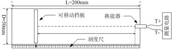
[0015] refer to figure 1 , Install the transducer coaxially in a closed pipeline with a length of 200mm and a diameter of 50mm, and the inside is air at normal temperature and pressure. The baffle in the pipe can move axially to adjust the length of the sound wave reflection path. The two pins T+ and T- of the ultrasonic sensor to be tested are connected to the circuit.

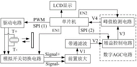
[0016] refer to figure 2 , the working process of the whole system is: the SPI (1) communication interface of the single-chip microcomputer adjusts the digital potentiometer, changes the driving voltage, and generates a PWM control driving circuit at the same time, so that the transducer obtains the excitation voltage T+ and T-. The microcontroller controls the timing of the analog switch switching circuit through the EN1 port, so that the transducer enters the receiving state after being excited. After the ...


PUM


Abstract

The invention discloses a measurement method for ultrasonic transducer signal and a circuit, and is used for the conformance testing of ultrasonic transducer signals in ultrasonic flowmeter measurement. In the measurement method, the transducer is put into an airtight container, a baffle plate with adjustable acoustic wave path length is arranged in the container according to the design. The voltage, pulse count, frequency, and duty cycle of the excitation signals are adjusted, and then the reflected echo signals are processed. The processing circuit comprises a preamplifier circuit, a filter circuit, a gain control circuit and a peak-sampling circuit. The echo signals are stabilized in the same peak value by a digital AGC circuit formed by the gain control circuit and the peak value through the circuit, finally the parameters of the transducer are determined according to the magnification times of the echo signals, and a basis is provided for transducer pairing. Meanwhile, according to the changes of the sonic path distance under the same incentives condition, the measurement method can be used for the selection of different pipe diameter flowmeter transducers. The measurement method for the ultrasonic transducer signal and the circuit has the advantages of low cost, low power consumption, measuring stability and high resolution.

Description

technical field [0001] The invention belongs to the field of detection of ultrasonic transducers and is applied to the test of the consistency of transducer signals in ultrasonic flowmeters. Background technique [0002] An ultrasonic transducer is an acoustic-electric conversion device widely used in ultrasonic flowmeters. The ultrasonic flowmeter uses the received ultrasonic signal to calculate the flow information. It is a non-contact flowmeter with outstanding advantages such as small pressure loss, high precision, and large range ratio. It has broad application in international trade and engineering applications. prospect. [0003] The so-called consistency of the transducer refers to the similarity of the static and dynamic characteristics of the two transducers. If the consistency of the two ultrasonic transducers selected is poor, the two sound channels of the transducers will be quite different, resulting in differences in parameters such as the shape, amplitude, ...

Claims


Application Information

Patent Timeline
Patent Type & Authority Applications(China)
IPC IPC(8): G01F1/66
CPCG01F1/667
Inventor 赵伟国虞结勇章圣意林景殿黄朝川李中阳
Owner CHINA JILIANG UNIV
Why Eureka
Try Eureka