Stroke detection and debugging method of guide vane control loop with pressure distribution valve

A stroke detection and control loop technology, applied in the field of stroke detection and debugging of the guide vane control loop with pressure distribution valve, can solve the problems of complex, missing, and change of the guide vane control loop, etc., so as to facilitate later maintenance and maintenance. The effect of debugging

Active Publication Date: 2017-05-31
广东蓄能发电有限公司
View PDF5 Cites 19 Cited by
  • Summary
  • Abstract
  • Description
  • Claims
  • Application Information

AI Technical Summary

Problems solved by technology

[0003] 1) Manufacturers do not have a unified method when designing the detection method for the pressure distribution valve of the governor system for the power plant. They often design a model similar to that of the units that have been put into operation based on the experience of engineers. However, due to the lack of experience, the method has not been formed , so it is easy to have various problems in the early stage of design and operation, such as the detection method does not meet the requirements of on-site installation, the sensor works in the non-linear area, etc.
[0004] 2) In the guide vane control circuit, in addition to the calibration of the sensor, two zero points need to be paid special attention to, one is the electrical zero point of the electro-hydraulic converter, and the other is the control zero point of the main pressure distribution valve. Since these two zero points are parallel It is not the zero point or midpoint of physical detection, but the "balance position" when the guide vane is not opened or closed. Therefore, after the installation of the guide vane control circuit is completed, it is necessary to compensate the two zero points and set compensation parameters. Because the guide vane The leaf control loop is complex and requires professionals to debug for a long time before obt...

Method used


Image

  • Stroke detection and debugging method of guide vane control loop with pressure distribution valve
  • Stroke detection and debugging method of guide vane control loop with pressure distribution valve

Examples


Embodiment 1

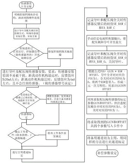
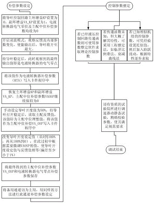
[0045] Such as Figure 1-2 As shown, a guide vane control circuit stroke detection and debugging method with a pressure distribution valve includes the following steps:

[0046] S1: Design the guide vane control block diagram according to the mechanical equipment structure of the pumped storage unit, and use the two-stage amplification method of the electro-hydraulic converter and the pressure distribution valve to drive the guide vane servomotor to move through the oil pressure; therefore, the general design in the guide vane control circuit Cascaded way;

[0047] S2: Determine the stroke detection method of the guide vane servomotor and the main pressure distribution valve;

[0048] S3: making and installing a linkage mechanism and a sensor, the sensor is used to detect the stroke of the main pressure distribution valve and the guide vane, and the linkage mechanism is used to convert the stroke of the main pressure distribution valve and the guide vane into the measuring st...


PUM


Abstract

The invention provides a stroke detection and debugging method of a guide vane control loop with a pressure distribution valve. The method includes the following steps that: a guide vane control block diagram is designed according to the equipment structure of a pumped-hydro energy storage unit, and an electro-hydraulic converter and pressure distribution valve two-stage amplification mode is adopted to make a guide vane servomotor to act through oil pressure; guide vane servomotor and main pressure distribution valve stroke detection modes are determined; a linkage mechanism and a sensor are manufactured and installed, wherein the sensor is used for detecting the strokes of a main pressure distribution valve and a guide vane, and the linkage mechanism is used for converting the strokes of the main pressure distribution valve and the guide vane into the measurement strokes of the sensor; sensor calibration is performed on the guide vane and the main pressure distribution valve; the zero position of an electro-hydraulic converter and the compensation parameter of the neutral position of the main pressure distribution valve are obtained; and guide vane static reaction testing is performed, the acting condition of the guide vane is observed, and the compensation parameter is finely adjusted, so that guide vane control offset can be minimized; and control parameter setting is performed. With the method adopted, it can be ensured that the guide vane control closed-loop is within a reasonable range and has a certain margin, and therefore, later-stage maintenance and debugging can be facilitated.

Description

technical field [0001] The invention relates to the control field of a pumped storage unit, and more specifically, to a method for detecting and debugging the stroke of a guide vane control circuit with a pressure distribution valve. Background technique [0002] The pumped storage unit plays an important role in frequency modulation and phase modulation, peak shaving and valley filling, emergency backup, stabilizing power system voltage and cycle, and ensuring the operation efficiency of thermal power and nuclear power units in the power grid. Improving the economy and stability of the power grid is becoming more and more important. The speed control system is one of the core systems to realize the operation control of the pumped storage unit, and the guide vane position control circuit is the direct output circuit of the governor. Once a failure occurs, it will cause serious consequences such as failure to start or stop the unit, tripping, etc. . In order to improve the ...

Claims


Application Information

Patent Timeline
IPC IPC(8): G01M13/00F03B15/00
CPCF03B15/00G01M13/00Y02E10/20Y02P70/50
Inventor 吴昊杨铭轩冯凌云巩宇代雄梁彦徐陶龙邱小波
Owner 广东蓄能发电有限公司
Why Eureka
Try Eureka