Supercharge Your Innovation With Domain-Expert AI Agents!

Welding seam eddy current detection test block and manufacturing method thereof

A technology of eddy current testing and manufacturing methods, applied in the direction of material magnetic variables, etc., can solve problems such as inability to realize live detection, affect detection results, and unsuitable rays

Pending Publication Date: 2017-05-31
STATE GRID CORP OF CHINA +3
View PDF7 Cites 14 Cited by
  • Summary
  • Abstract
  • Description
  • Claims
  • Application Information

AI Technical Summary

Problems solved by technology

[0004] Since the GIS equipment is a metal fully enclosed switchgear, there are many difficulties in the non-destructive testing of the weld seam of the live GIS equipment cylinder, because there are different structures inside, and the on-site detection position is limited, the ray is not suitable for the weld seam of the GIS equipment cylinder For the two surface detection methods of magnetic particle and penetration, the field application of the magnetic particle method is very simple, and it can directly detect surface defects, but it cannot realize live detection; the outer surface of the cylinder of the on-site GIS equipment is coated with a thick layer of paint and cannot be polished, so The penetration testing method is also not applicable; the ultrasonic method is very effective for the detection of internal defects of the weld, but a coupling agent is required for the detection, and the surface paint will affect the detection result, and the detection efficiency is low. It is not suitable for the detection of a 5000m long weld in a substation

Method used


Image

  • Welding seam eddy current detection test block and manufacturing method thereof
  • Welding seam eddy current detection test block and manufacturing method thereof
  • Welding seam eddy current detection test block and manufacturing method thereof

Examples


Embodiment 1

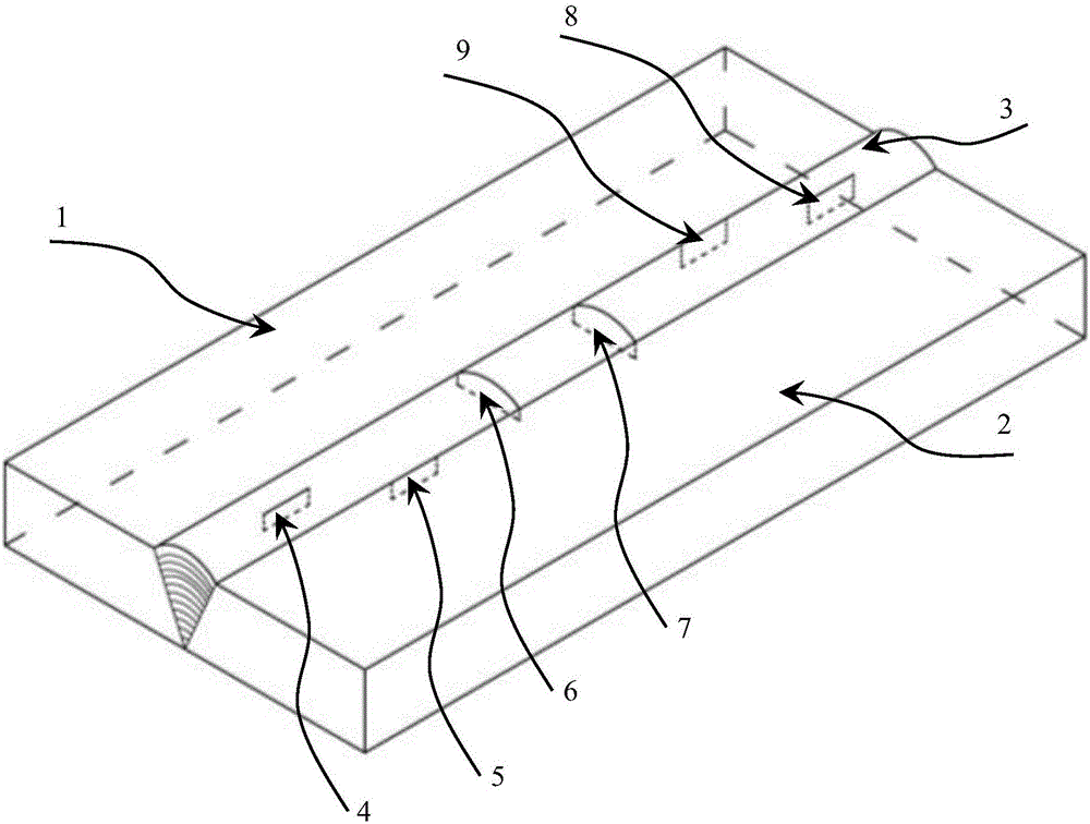
[0043] refer to figure 1 , a method for making a weld seam eddy current test block is as follows:

[0044] The first step: processing the groove on the corresponding side of the test block base 1 and the test block base 2; the second step: butt welding the grooves of the test block base 1 and the test block base 2 2; the third step: welding Brush the paint on the base of the good test block; the fourth step: use EDM to process 8 non-transparent artificial grooves.

[0045] The weld seam eddy current testing test block includes: test block base 1, test block base 2 2, weld 3 and several crack structures; test block base 1 and test block base 2 are butt welded, and weld 3 is located on the test block Between base one 1 and test block base two 2; weld reinforcement 2 mm; test block thickness 8 mm; the surface of the test block is a paint layer. The crack structure is a non-transparent artificial groove, including groove one 4, groove two 5, groove three 6, groove four 7, groove...

Embodiment 2

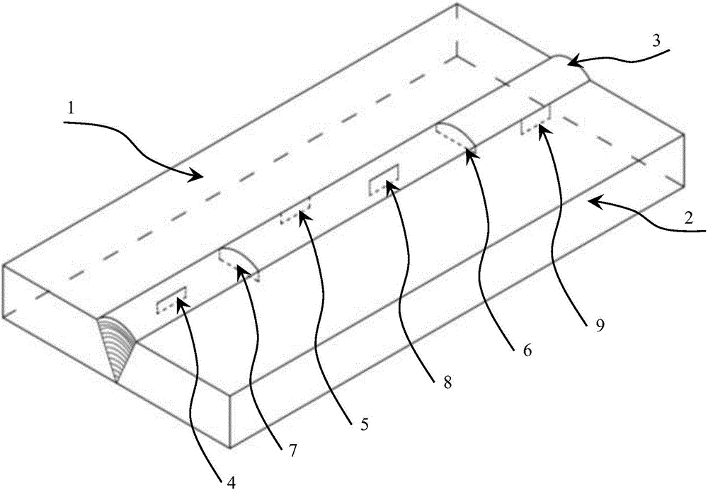
[0051] refer to figure 2 , a method for making a weld seam eddy current test block is as follows:

[0052] The first step: processing the groove on the corresponding side of the test block base 1 and the test block base 2; the second step: butt welding the grooves of the test block base 1 and the test block base 2 2; the third step: welding Brush the paint on the base of the good test block; the fourth step: use EDM to process 8 non-transparent artificial grooves.

[0053]The weld seam eddy current testing test block includes: test block base 1, test block base 2 2, weld 3 and several crack structures; test block base 1 and test block base 2 are butt welded, and weld 3 is located on the test block Between base one 1 and test block base two 2; weld reinforcement 2 mm; test block thickness 8 mm; the surface of the test block is a paint layer. The crack structure is a non-transparent artificial groove, including groove one 4, groove four 7, groove two 5, groove five 8, groove ...

Embodiment 3

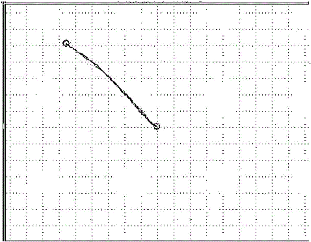
[0059] Waveform diagram analysis of groove contrast sample defect detection

[0060] refer to image 3 , Figure 4 , Figure 5 , Figure 6 and Figure 7 , for the analysis of detection waveforms of 1mm deep defects in four different comparison test blocks, the defect wave sensitivity of the base metal is the highest, the waveform has no width, and the angle difference from the interference wave angle of the weld itself is the largest, which is about 20°; Due to the influence of weld waves in the longitudinal and transverse defects, the sensitivity is 2dB lower than that of the base metal defect, and the waveform has some width; when detecting defects in the heat-affected zone of the weld, in addition to selecting the probe parallel to the weld in the heat-affected zone In addition to the (longitudinal) scanning, the horizontal scanning of the probe and the weld should be added. Since the flat probe of about Φ15mm is selected, the defects near the edge of the weld will be m...


PUM

PropertyMeasurementUnit
widthaaaaaaaaaa

Abstract

The invention belongs to the field of nondestructive detection, and in particular provides a welding seam eddy current detection test block. The invention also relates to a manufacturing method of the welding seam eddy current detection test block. The welding seam eddy current detection test block comprises: a first test block matrix 1, a second test block matrix 2, a welding seam 3 and a plurality of crack structures, wherein the first test block matrix 1 and the second test block matrix 2 are butt-welded, and the welding seam 3 is located between the first test block matrix 1 and the second test block matrix 2. The manufacturing method of the test block comprises: chamfering the test block matrices; butt-welding chamfers of the test block; printing the test block matrices with oil paint; processing artificial grooves. According to the welding seam eddy current detection test block and the manufacturing method thereof, the size of a true crack of a detected piece can be effectively simulated; the welding seam eddy current detection test block for eddy current detection is basically consistent with the detected piece in texture, shape, heat treatment state and surface state, and the welding seam eddy current detection test block has an artificial detect which is up to an inspection standard, and can be effectively used for setting the inspection sensitivity and evaluating the magnitude of the defect.

Description

technical field [0001] The invention belongs to the field of non-destructive testing, and in particular provides a weld seam eddy current test block, and the invention also relates to a production method of the weld seam eddy current test block. Background technique [0002] Gas-insulated metal-enclosed switchgear (GIS) is composed of circuit breakers, disconnectors, grounding switches, transformers, lightning arresters, busbars, connectors, and outlet terminals. SF filled with a certain pressure 6 A closed combination electrical appliance in which insulating gas is used as an insulating and arc-extinguishing medium. GIS is not only widely used in the field of high voltage and ultra-high voltage, but also in the field of ultra-high voltage. Compared with conventional open substations, GIS has the advantages of compact structure, small footprint, high reliability, flexible configuration, convenient installation, strong safety, strong environmental adaptability, and small ma...

Claims


Application Information

Patent Timeline
Patent Type & Authority Applications(China)
IPC IPC(8): G01N27/90
CPCG01N27/9006
Inventor 何喜梅王志惠陈文强刘高飞张烁贾生旭施勇李玉海闫斌邓大勇李生平付宣蓉陈莲君杨艳榕
Owner STATE GRID CORP OF CHINA
Features
  • R&D
  • Intellectual Property
  • Life Sciences
  • Materials
  • Tech Scout
  • Unparalleled Data Quality
  • Higher Quality Content
  • 60% Fewer Hallucinations
Learn More