
A processing method for signal distortion of magnetoelectric speed sensor

A speed sensor and processing method technology, applied in the field of signal processing, can solve the problems such as waveform distortion, normal value display and deviation of the output signal of the magnetoelectric speed sensor, so as to solve the problem of signal distortion of the magnetoelectric speed sensor, short processing time, Easy to get effects

Active Publication Date: 2020-08-04
SHENYANG LIMING AERO-ENGINE GROUP CORPORATION
View PDF5 Cites 0 Cited by
  • Summary
  • Abstract
  • Description
  • Claims
  • Application Information

AI Technical Summary

Problems solved by technology

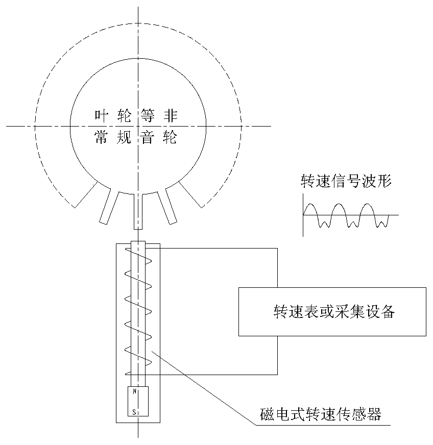
[0003] In the actual scientific research and production process, due to structural or other design reasons, sometimes there is no gear or sound wheel for speed measurement in the shaft system of the rotor to be tested, so the rotor can only be sensed by the magnetic speed sensor directly. At this time, it is likely to bring about a problem: since the blades are thin-sheet parts, the distance between the blades may be much larger than the thickness of the blades, which is far from the requirements of the tooth shape of the speed sound wheel of the magnetoelectric speed sensor, which will inevitably lead to magnetoelectric speed. The distortion of the output signal waveform of the speed sensor, the typical waveform is as follows figure 2 In the situation shown, different tachometers or acquisition devices may obtain different results after processing this distorted signal: the numerical display is normal, the numerical display jumps wildly, or there is a large deviation from the actual rotational speed (usually doubled), etc.
If it is the latter two cases, it is obvious that the system cannot be used normally

Method used


Image

  • A processing method for signal distortion of magnetoelectric speed sensor
  • A processing method for signal distortion of magnetoelectric speed sensor
  • A processing method for signal distortion of magnetoelectric speed sensor

Examples


Embodiment Construction

[0032] An embodiment of the present invention will be described in detail below in conjunction with the accompanying drawings.

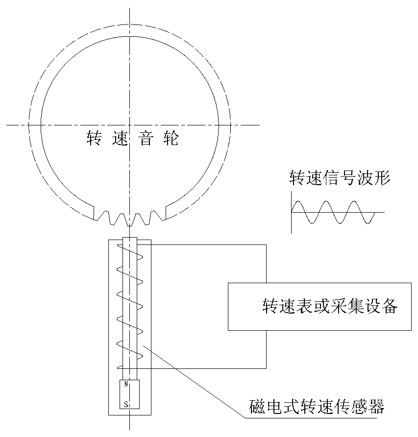
[0033] The low-pressure rotor speed measurement sensor of an aero-derivative gas turbine is installed on the cylinder (casing) at the tip of the first-stage rotor blade, and the magnetic-conductive first-stage rotor blade sweeps the magnetoelectric speed sensor and generates an AC voltage signal Output, the gas turbine control system calculates the speed of the low-pressure rotor by collecting the signal, the system is composed as follows figure 2 shown.

[0034] Because the structural shape of the low-pressure first-stage rotor blade tip of the gas turbine sweeps over the speed measurement sensor is very different from the conventional transmission gear, such as Figure 4 The signal waveform shown will cause abnormal (unstable or doubled) phenomenon in the displayed rotational speed data. The reason is that an "extra" small sine wave appears at t...


PUM


Abstract

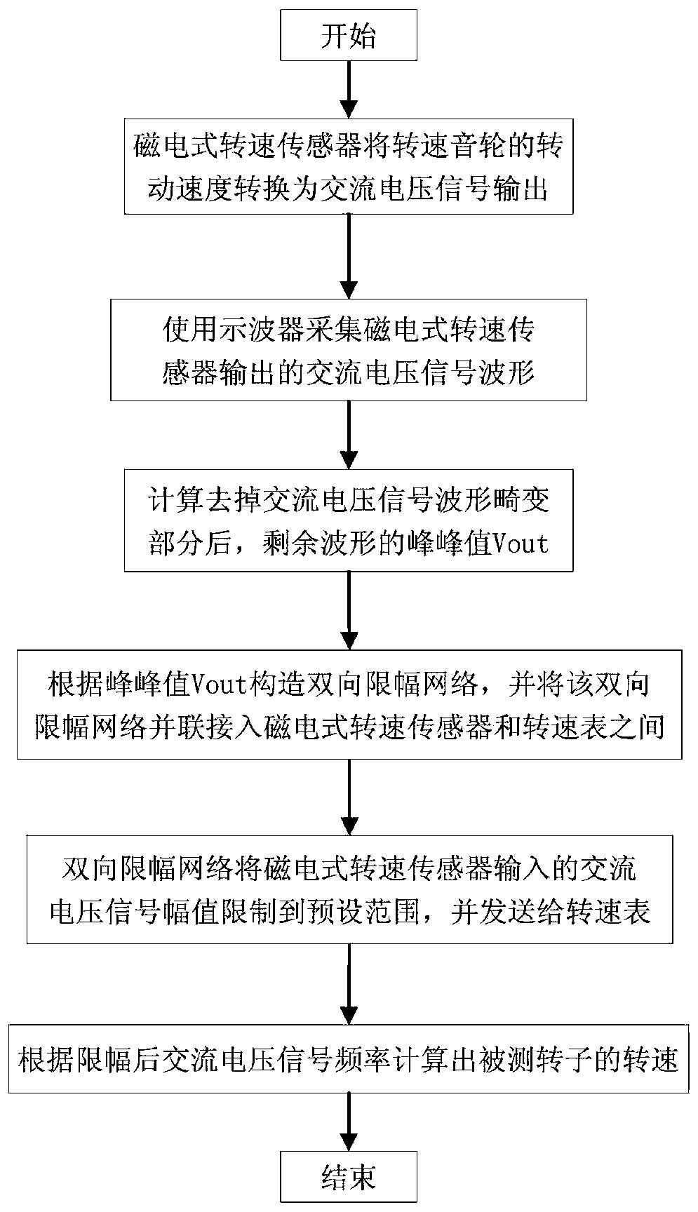
An electromagnetic type speed sensor signal distortion processing method belongs to the signal processing technical field, and comprises the following steps: using an electromagnetic type speed sensor to convert a rotate speed phonic wheel rotate speed into an AC voltage signal, and outputting same; using an oscilloscope to collect the AC voltage signal waveform outputted by the electromagnetic type speed sensor; calculating and removing the AC voltage signal waveform distortion portion, and leaving the waveform peak-to-peak value Vout; using the peak-to-peak value Vout to build a bidirectional amplitude limit network, and parallelly connecting the bidirectional amplitude limit network between the electromagnetic type speed sensor and a revolution meter; using the bidirectional amplitude limit network to limit the AC voltage signal amplitude inputted by the electromagnetic type speed sensor into a preset range; using the revolution meter to calculate the rotating speed of a tested rotor according to the AC voltage signal frequency after amplitude limitation. The method can solve the electromagnetic type speed sensor signal distortion problems caused by an irregular rotate speed phonic wheel, is easy in material taking, short in processing time, and fast in effectiveness.

Description

technical field [0001] The invention belongs to the technical field of signal processing, and in particular relates to a processing method for signal distortion of a magnetoelectric rotational speed sensor. Background technique [0002] Conventional speed measurement / acquisition systems such as figure 1 As shown, it is usually composed of a speed tone wheel mechanically connected to the rotor under test, a magnetoelectric speed sensor, a measuring line, and a tachometer or acquisition device. When the teeth on the magnetic speed sound wheel sweep over the sensitive end of the speed sensor, The magnetic field strength of the iron core of the speed sensor with a permanent magnet inside changes alternately, so that an AC induced voltage that is completely consistent with the frequency of the tooth top of the sound wheel at the sensitive end of the sensor can be generated at both ends of the coil lead wire of the speed sensor. The rotational speed of the measured rotor can be o...

Claims


Application Information

Patent Timeline
Patent Type & Authority Patents(China)
IPC IPC(8): G01P3/44
CPCG01P3/44
Inventor 肖印波于鑫张旭光袁正兴张立南
Owner SHENYANG LIMING AERO-ENGINE GROUP CORPORATION
Learn More