Planar magnetic field scanning imaging system based on active/passive composite shielding

A composite shielding and scanning imaging technology, applied in the size/direction of the magnetic field, the use of superconducting devices for magnetic field measurement, material magnetic variables, etc. problems, to achieve the effect of shielding the interference of low-frequency and intermediate-frequency magnetic fields, excellent shielding ability, and convenient movement

Inactive Publication Date: 2017-05-31
BEIHANG UNIV
View PDF6 Cites 6 Cited by
  • Summary
  • Abstract
  • Description
  • Claims
  • Application Information

AI Technical Summary

Problems solved by technology

The detection sensitivity of this detection method is relatively high, and it can be detected in high temperature conditions, narrow areas of the workpiece, deep hole walls, etc., but the detection system needs to be equipped with an additional excitation coil to excite the sample to be tested, and according to different samples to be tested Choosing different excitation signals is contradictory to the detection depth and detection sensitivity. When performing eddy current detection on a material, it must be considered comprehensively according to the material, surface state, and inspection standards, and then determine the detection plan and technical parameters.
[0004] Especially in the weak magnetic field imaging research of the pT level, there are the following shortcomings: first, due to the inverse proportional attenuation of the magnetic field with the cube of the distance, it is difficult to implement long-distance fault diagnosis; second, the detection system signal noise Compared with higher requirements, it is difficult for general fluxgate meters and GMR\GMI to meet the requirements

Method used


Image

  • Planar magnetic field scanning imaging system based on active/passive composite shielding
  • Planar magnetic field scanning imaging system based on active/passive composite shielding

Examples


Embodiment Construction

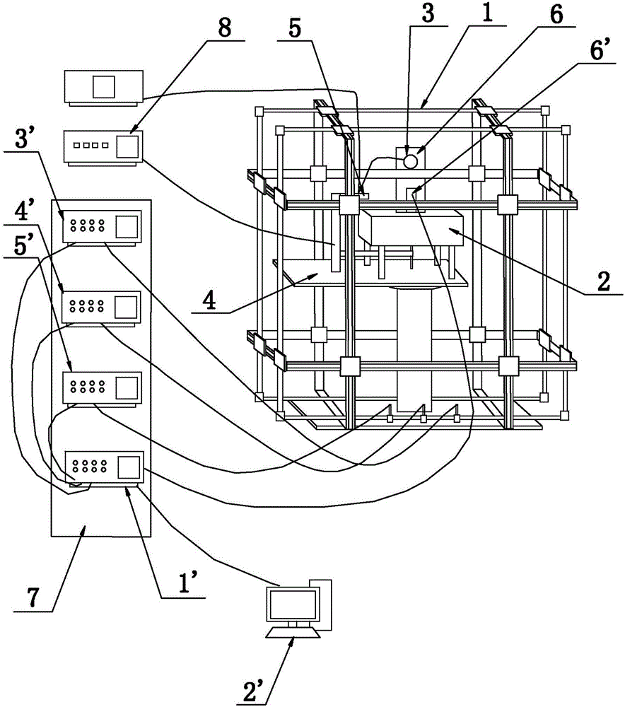
[0014] Such as figure 1 As shown, it is a schematic structural view of the planar magnetic field scanning imaging system based on active and passive composite shielding of the present invention, including a host computer 2', an active magnetic shielding device 1, a three-dimensional mobile platform 4 and a superconducting quantum interferometer magnetic sensor 3, along the horizontal direction The provided three-dimensional mobile platform 4 is installed inside the active magnetic shielding device 1 , and the control terminal of the three-dimensional mobile platform 4 is connected to the control signal output terminal of the external three-dimensional mobile platform controller 8 . The active magnetic shielding device 1 is internally provided with a low-temperature Dewar device 6, and the low-temperature Dewar device 6 is internally provided with a superconducting quantum interferometer magnetic sensor 3, and the control terminal of the superconducting quantum interferometer ma...


PUM


Abstract

The invention relates to a planar magnetic field scanning imaging system based on active / passive composite shielding and is intended to provide a planar magnetic field scanning imaging system simple in structure, good in measurement signal accuracy and high in stability. The planar magnetic field scanning imaging system comprises an upper computer, an active magnetic shielding device, a three-dimensional moving platform and a superconducting quantum interferometer magnetic sensor; the three-dimensional moving platform is installed in the active magnetic shielding device, the control end of the three-dimensional moving platform is connected with the control signal output end of a three-dimensional moving platform controller, the superconducting quantum interferometer magnetic sensor is also disposed in the active magnetic shielding device, the control end of the superconducting quantum interferometer magnetic sensor is connected with the control signal output end of a sensor controller, and the control end of the upper computer is connected respectively to the control signal receiving ends of the three-dimensional moving platform controller, sensor controller and active shielding controller.

Description

technical field [0001] The invention relates to the field of magnetic shielding, in particular to a planar magnetic field scanning imaging system based on active and passive composite shielding. Background technique [0002] In high-performance passive magnetic shielding, the change of the shape of the magnetic shielding body has an impact on the shielding effect, and the shielding factor is affected by the external field, and there is a certain dependence between the two. [0003] Magnetic particle flaw detection needs to magnetize the workpiece made of magnetic materials such as steel, and use the magnetic leakage energy of the defective part to absorb the characteristics of magnetic powder, and display the surface defects and near-surface defects of the detected object according to the distribution of magnetic powder. The characteristic of this flaw detection method is that the display is intuitive, but it needs to magnetize the component to be tested, which takes a long ...

Claims


Application Information

Patent Timeline
IPC IPC(8): G01R33/035G01N27/82
CPCG01R33/035G01N27/82
Inventor 王三胜李园园
Owner BEIHANG UNIV
Why Eureka
Try Eureka