Connector for carbon-fiber composite-core optical-fiber wires

A technology of wire connectors and composite cores, applied in light guides, optics, instruments, etc., can solve problems such as fiber shedding, achieve the effects of increasing the contact area, improving fastening performance, and avoiding bending

Inactive Publication Date: 2017-05-31
STATE GRID HENAN ELECTRIC POWER ELECTRIC POWER SCI RES INST +1
View PDF7 Cites 2 Cited by
  • Summary
  • Abstract
  • Description
  • Claims
  • Application Information

AI Technical Summary

Problems solved by technology

The disadvantage of this structure is that after the optical fiber to be connected is inserted into the inner end hole 5B, there is a risk of the optical fiber falling off because there is no pressing or squeezing device

Method used


Image

  • Connector for carbon-fiber composite-core optical-fiber wires
  • Connector for carbon-fiber composite-core optical-fiber wires
  • Connector for carbon-fiber composite-core optical-fiber wires

Examples


Embodiment 1

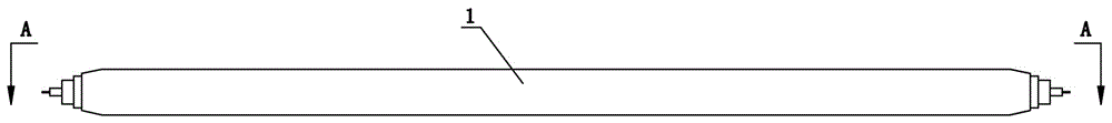
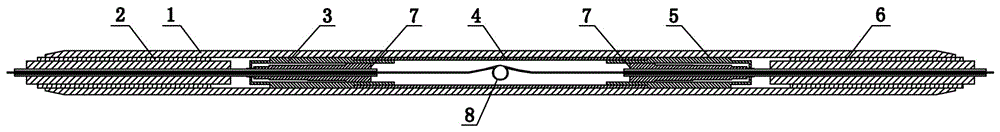
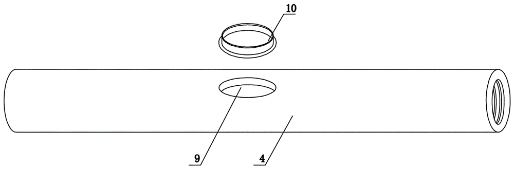
[0030] Such as Figure 1 to Figure 3 As shown, the present invention includes an outer crimping pipe 1, which is an integrally formed hollow pipe, and the outer crimping pipe 1 is provided with a first inner lining pipe 2, a first wedge-shaped clamp support 3, and a connecting rod in sequence from left to right. The pipe 4, the second wedge-shaped clamp support 5 and the second liner pipe 6, the first wedge-shaped clamp support 3 and the second wedge-shaped clamp support 5 are all provided with matching wedge-shaped clamps 7, and the front end surface of the connecting pipe 3 is opened Operation hole 9, the operation hole 9 is oval, the operation hole 9 is provided with a sealing cover 10, the inner wall of the connecting pipe 4 is coated with a rubber coating (not shown), and its inner wall is smooth.

[0031] When this structure is in use, the operation hole 9 is easy to improve the work efficiency in the process of welding the inner cores of two optical fiber wires. During ...

Embodiment 3

[0037] A splicing method based on the carbon fiber composite core optical fiber lead splice in embodiment 2, comprising the following steps:

[0038] Step 1: Strip the insulation layer and protective layer of the two optical fiber wires to expose the inner core of the optical fiber in the inner layer;

[0039] Step 2: Pass one of the optical fiber wires through the outer crimping tube, and then pass the free end of the inner core of the left optical fiber through the first inner lining tube and the wedge-shaped clip to make it protrude from the connecting tube and out of the operation hole, and insert the right side The free end of the optical fiber inner core passes through the second inner liner and the wedge-shaped clamp respectively to make it protrude from the connection tube and out of the operation hole. In the clamp, the unstripped part of the right fiber optic wire is located in the second inner liner and the wedge-shaped clamp on the right, and the free ends of the t...


PUM


Abstract

The invention belongs to the technical field of carbon-fiber wires and particularly relates to a connector for carbon-fiber composite-core optical-fiber wires. The connector comprises an outer pressure connecting tube and is characterized in that the outer pressure connecting tube is of a hollow structure, a first lining tube, a first wedge clamp support, a connecting tube, a second wedge clamp support and a second lining tube are sequentially arranged in the outer pressure connecting tube from left to right, matched wedge clamps are arranged in the first wedge clamp support and the second wedge clamp support, the front end face of the connecting tube is provided with an operation hole, the inner wall of the connecting tube is provided with rubber coating, and the operation hole is provided with a sealing cover. The connector has the advantages that fast reconnection of the carbon-fiber composite-core optical-fiber wires is achieved by the operation hole, and the effect of long-distance and high-performance signal transmission is guaranteed.

Description

technical field [0001] The invention belongs to the technical field of carbon fiber wires, in particular to a carbon fiber composite core optical fiber wire connector. Background technique [0002] The research on carbon fiber composite core optical fiber conductors (hereinafter referred to as optical fiber conductors) began in the 1990s and was developed by Japanese scholars. In 2004, the United States first applied optical fiber conductors to power transmission lines. my country's research on optical fiber conductors began in 2005, and the first application of this conductor in my country was in the expansion and transformation of 220,000 lines in Liaoning and Fujian in 2006. Optical fiber wire has the characteristics of high strength, large carrying capacity, good heat resistance, small linear expansion coefficient, light weight, and good corrosion resistance. It is an energy-saving and environmentally friendly wire and has broad application prospects in overhead transmis...

Claims


Application Information

Patent Timeline
Patent Type & Authority Applications(China)
IPC IPC(8): G02B6/38G02B6/255
CPCG02B6/3825G02B6/2551G02B6/389
Inventor 张博李清李梦丽艾文君魏建林吕中宾卢明宋高丽杨威谢凯陈钊任鹏亮
Owner STATE GRID HENAN ELECTRIC POWER ELECTRIC POWER SCI RES INST
Why Eureka
Try Eureka