Transmission type digital holography microimaging device based on electrical-controlled switchable focus lens

A digital holographic microscope and imaging device technology, applied in the direction of instruments, can solve problems such as inability to guarantee system stability, achieve the effects of ensuring stability and practicability, eliminating phase distortion, and avoiding mechanical movement

Inactive Publication Date: 2017-05-31
SHENZHEN UNIV
View PDF5 Cites 6 Cited by
  • Summary
  • Abstract
  • Description
  • Claims
  • Application Information

AI Technical Summary

Problems solved by technology

Another method is to introduce an ordinary lens in the reference light path, and adjust the position of the lens to generate spherical waves with different curvatures to match the curvature of the microscope objective lens, but the above two methods require mechanical movement of the lens
[0006] Therefore, in the case of introducing a microscopic objective lens, it is necessary to mechanically move the lens to eliminate the phase distortion caused by the microscopic objective lens; and, when measuring different samples, on the one hand, it is necessary to manually switch between objective lenses with different magnifications for imaging , on the other hand, it is also necessary to move the lens mechanically to eliminate the phase distortion caused by the microscopic objective lens, which cannot guarantee the stability of the system

Method used


Image

  • Transmission type digital holography microimaging device based on electrical-controlled switchable focus lens
  • Transmission type digital holography microimaging device based on electrical-controlled switchable focus lens
  • Transmission type digital holography microimaging device based on electrical-controlled switchable focus lens

Examples


Embodiment Construction

[0035] In order to make the object, technical solution and advantages of the present invention clearer, the present invention will be further described in detail below in conjunction with the accompanying drawings and embodiments. It should be understood that the specific embodiments described here are only used to explain the present invention, not to limit the present invention.
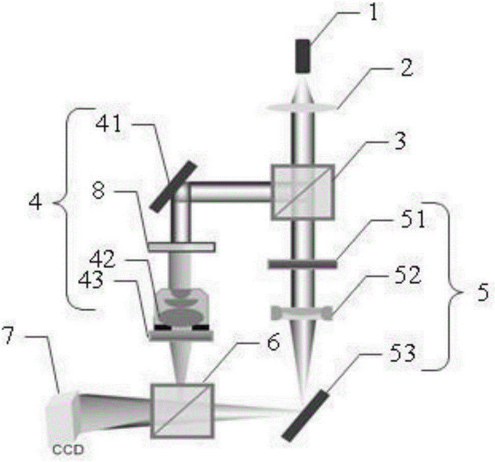
[0036] The main realization idea of ​​the present invention is: use the first beam splitter to separate the incoming laser light into object light and reference light, after the light in the object light path passes through the transparent sample to be tested and the microscopic objective lens, the object light spherical wave is formed; In the optical path of the reference light, because of the introduction of the electronically controlled zoom lens, the focal length of the electronically controlled zoom lens can be adjusted by adjusting the current, thereby generating a spherical wave of the refere...


PUM


Abstract

The invention is suitable for the technical field of optical imaging and measuring, and provides a transmission type digital holography microimaging device based on an electrical-controlled switchable focus lens. The transmission type digital holography microimaging device based on the electrical-controlled switchable focus lens comprises a laser device, a first beam splitter, a first light path turning assembly, a second light path turning assembly, a second beam splitter and a camera, wherein the first beam splitter is used for separating laser emitted from the laser device into object light and reference light; the first light path turning assembly is used for guiding the transmitting direction of an object light spherical wave generated after the object light passes through a microobjective to the second beam splitter; the electrical-controlled switchable focus lens in the second light path turning assembly is used for changing a focal length and enabling the curvature of a reference light spherical wave formed after the reference light passes through the electrical-controlled switchable focus lens to be the same as the curvature of the object light spherical wave; the second light path turning assembly is used for guiding the transmitting direction of the reference light spherical wave to the second beam splitter; the second beam splitter is used for outputting the spherical wave; and the camera is used for recording a formed interferogram. By the device, phase distortion can be eliminated.

Description

technical field [0001] The invention belongs to the technical field of optical imaging and measurement, in particular to a transmission digital holographic microscopic imaging device based on an electronically controlled zoom lens. Background technique [0002] As an important means of quantitative phase measurement, digital holographic microscopic imaging technology can use a hologram to independently obtain quantitative amplitude information and phase information of an object at the same time, realizing real-time dynamic, high-resolution, non-invasive measurement. This technology is widely used in stress measurement, living cell observation, three-dimensional measurement of microstructure devices, etc. [0003] Digital holographic microscopy technology can improve the lateral resolution of the measurement system due to the introduction of the microscopic objective lens. Microscopic objectives with different magnifications can be used in the measurement of different sample...

Claims


Application Information

Patent Timeline
Patent Type & Authority Applications(China)
IPC IPC(8): G03H1/00G03H1/04G03H1/08G03H1/10
CPCG03H1/0005G03H1/0443G03H1/0866G03H1/10G03H2001/0038
Inventor 彭翔邓定南彭军政刘晓利何文奇
Owner SHENZHEN UNIV
Why Eureka
Try Eureka