Potentiometer automatic assembly machine

An automatic assembly machine and potentiometer technology, which is applied to resistors, sliding contact resistors, circuits, etc., can solve the problems of short service life, high replacement cost, and low machining accuracy of potentiometer assembly machines.

Active Publication Date: 2017-05-31
广东钺河智能科技有限公司
View PDF7 Cites 11 Cited by
  • Summary
  • Abstract
  • Description
  • Claims
  • Application Information

AI Technical Summary

Problems solved by technology

However, the defects of this type of automatic assembly equipment in the prior art are as follows: First, the existing assembly machines for assembling and producing potentiometers have a low degree of automation, requiring a lot of manpower for assembly and production, and the assembly efficiency is low; The assembly and processing efficiency of the potentiometer assembly machine is low, the quantity of potentiometers assembled and produced per unit time is small, and the production cost is high; third, the processing accuracy of the existing potentiometer assembly machine is low, the connection of each component is not firm, and the yield rate of assembled potentiometers is high. Low, and the service life of the potentiometer is short; Fourth, the existing potentiometer assembly machine has a short service life and high replacement costs

Method used


Image

  • Potentiometer automatic assembly machine
  • Potentiometer automatic assembly machine
  • Potentiometer automatic assembly machine

Examples


Embodiment Construction

[0037] Attached below Figure 1-19 The present invention is described in further detail.

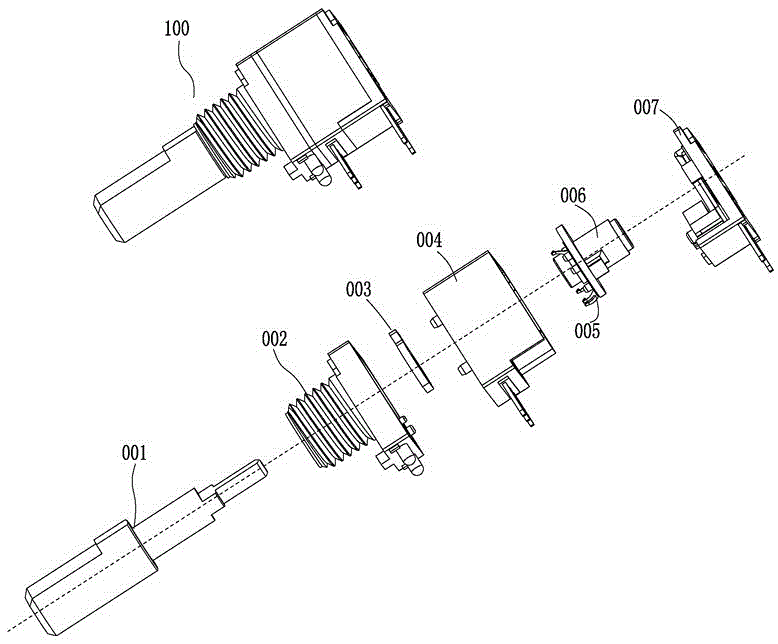
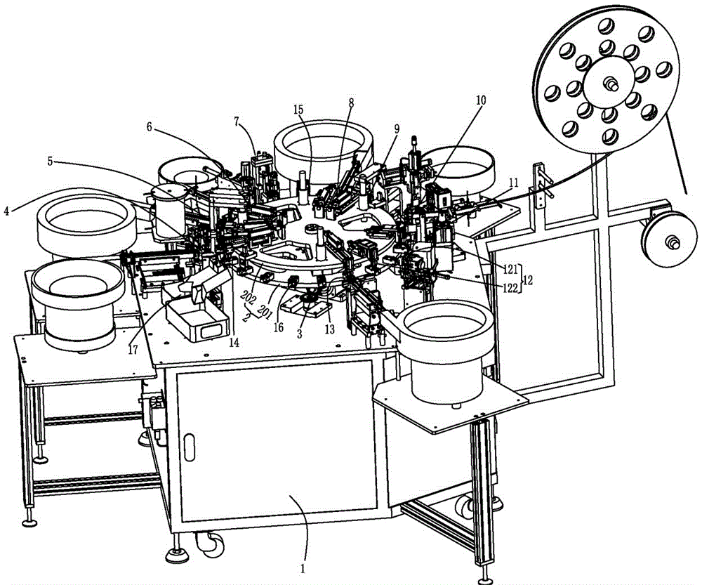
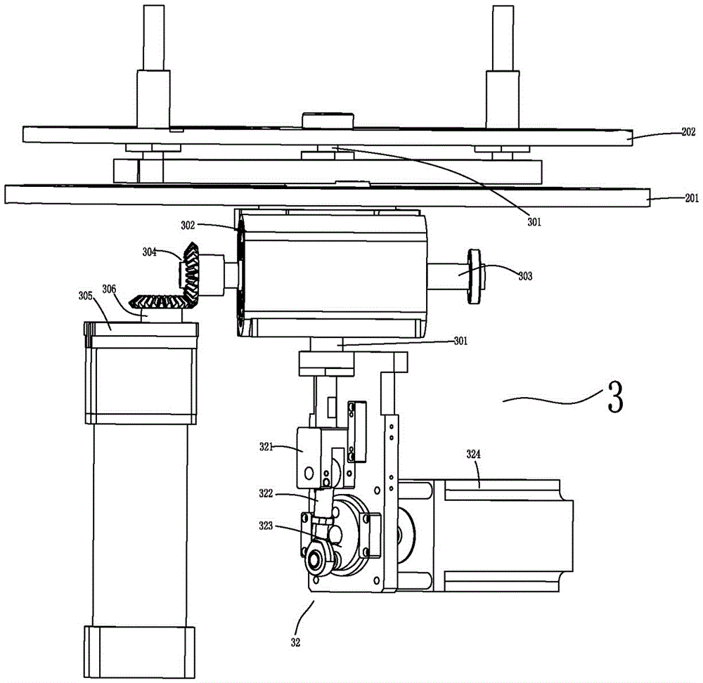
[0038] The present invention is an automatic assembly machine for potentiometers. Of course, the potentiometers assembled by the automatic assembly machine are not limited to walkie-talkies. As a specific embodiment of the application, refer to the attached Figure 1-3, the encoder automatic assembly machine of the present application includes a chassis 1. The top surface of the chassis 1 is an assembly workbench. In practice, after installing various mechanisms on the workbench, a chassis cover (not shown in the accompanying drawings) is also assembled, and a It is used to control the working controller of the automatic assembly machine, and the assembly machine is used to complete the assembly work of the potentiometer through the controller; the turntable 2 provided on the chassis 1, that is, on the workbench, includes a rotating disk 201 and a fixed disk 202. A cam divider assembly ...


PUM


Abstract

The invention discloses a potentiometer automatic assembly machine, which comprises a turntable, wherein the turntable comprises a rotatable disc and a fixed disc; the rotatable disc and the fixed disc can be driven to do corresponding intermittent rotation and intermittent ascending and descending by a cam cutter assembly; a shaft core feeding mechanism, a shaft sleeve feeding mechanism, a stop baffle sheet feeding mechanism, a stop baffle sheet riveting mechanism, a body feeding mechanism, a glue rotating sheet feeding mechanism, a brush feeding mechanism, a brush riveting mechanism, a glue rotating sheet installing mechanism, a switch feeding mechanism and a material return mechanism are arranged on a machine box; a plurality of part clamps are arrayed on the rotatable disc; during the assembly, the shaft core feeding mechanism applies oil on a shaft core and feeds the shaft core to the part clamps; an assembled stop baffle sheet and the shaft core are riveted by the stop baffle sheet riveting mechanism; a brush is riveted on a glue rotating sheet by the brush riveting mechanism; the glue rotating sheet riveted with the brush, the shaft core, a shaft sleeve, the stop baffle sheet and a body are assembled by the glue rotating sheet installing mechanism; the shaft sleeve, the stop baffle sheet, the body and a switch are sequentially assembled through the shaft sleeve feeding mechanism, the stop baffle sheet feeding mechanism, the body feeding mechanism and the switch feeding mechanism.

Description

technical field [0001] The invention relates to the field of electronic component processing equipment, in particular to an automatic assembly machine for potentiometers. Background technique [0002] With the development of technology in the fields of computers, home appliances, lathes, and automobiles, encoders are more and more widely used. Encoders are widely used in multimedia audio, household appliances, medical equipment, communication equipment, smart toys, instruments, walkie-talkies, reproduced audio and video, and mechanical equipment. They are mainly used to control the travel of moving parts and signal transmission. as attached Figure 1-2 As shown, in the prior art, the potentiometer 100 for adjusting the frequency band of the walkie-talkie mainly includes a shaft core 001, a shaft sleeve 002, a stop piece 003, a body 004, a rubber rotor 006, a brush 005 and a switch 007. Therefore, in order to make this kind of encoder, it is necessary to assemble the above-m...

Claims


Application Information

Patent Timeline
Patent Type & Authority Applications(China)
IPC IPC(8): H01C17/00H01C10/36
CPCH01C10/36H01C17/00
Inventor 曾河
Owner 广东钺河智能科技有限公司
Why Eureka
Try Eureka