
Plug device of bus duct

A plug-in device and busway technology, which is applied in the installation of busbars, docking busbars, cable installation, etc., can solve problems such as deterioration, inaccurate positioning, and sliding down of plug-in boxes, so as to reduce power loss and increase contact area effect

Active Publication Date: 2017-05-31
美嘉科技(镇江)有限公司
View PDF4 Cites 2 Cited by
  • Summary
  • Abstract
  • Description
  • Claims
  • Application Information

AI Technical Summary

Problems solved by technology

With the development of the electric power industry in the market, users have higher and higher requirements for the performance and appearance of such products, but there are hidden dangers in the structure design of the existing plug-in box, especially the safety during the use of the plug-in box. The fixing between the box and the busway is fixed with a pressure plate. The first is that the positioning is not accurate enough. The second is that the plug-in box is easy to slide down due to its own gravity and external force during use, resulting in deformation of the pins and accidents. ; At present, this structure needs to be changed so that there is a clear positioning between the busbar plug-in box and the busbar and the busway body can bear the weight of the plug-in box to ensure safe operation
[0004] The prior art also has the following problems: the number of ways to lead out the power disconnecting switch plug-in box is limited to the way of plugging and pulling out the claws and the way of binding conductors, wherein: (1) the plugging and pulling out of the claws is due to the contact surface of the busbar conductive body leading out the power supply It is too small and difficult to fix, which often leads to heat and high temperature at the pin position, resulting in insulation degradation and short circuit; (2) The design of the conductor lead-out binding structure cannot meet the needs of the owner to increase the lead-out plug-in box under normal power transmission operation (expandability) At the same time, it is not conducive to maintenance and repair, and the wiring work with the second measurement side requires the overall circuit power failure to increase the plug-in box or perform maintenance work; (3) All connections use a large number of screws to connect the phase sequence conductors, which is prone to accidents The risk of quality control arises, including the small phase sequence distance that leads to problems with insulation and withstand voltage

Method used


Image

  • Plug device of bus duct
  • Plug device of bus duct
  • Plug device of bus duct

Examples


Embodiment Construction

[0039] In order to make the above objects, features and advantages of the present invention more obvious and comprehensible, specific implementations of the present invention will be described in detail below in conjunction with the accompanying drawings.

[0040] In the following description, a lot of specific details are set forth in order to fully understand the present invention, but the present invention can also be implemented in other ways different from those described here, and those skilled in the art can do it without departing from the meaning of the present invention. By analogy, the present invention is therefore not limited to the specific examples disclosed below.

[0041] Second, "one embodiment" or "an embodiment" referred to herein refers to a specific feature, structure or characteristic that may be included in at least one implementation of the present invention. "In one embodiment" appearing in different places in this specification does not all refer to ...


PUM


Abstract

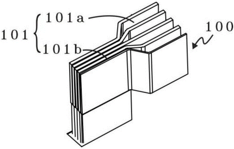
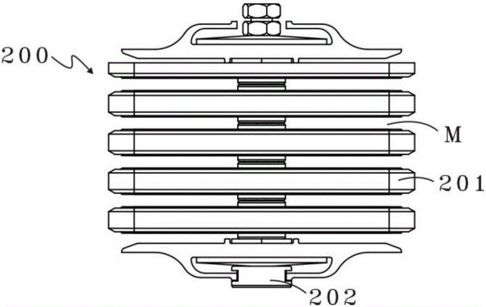
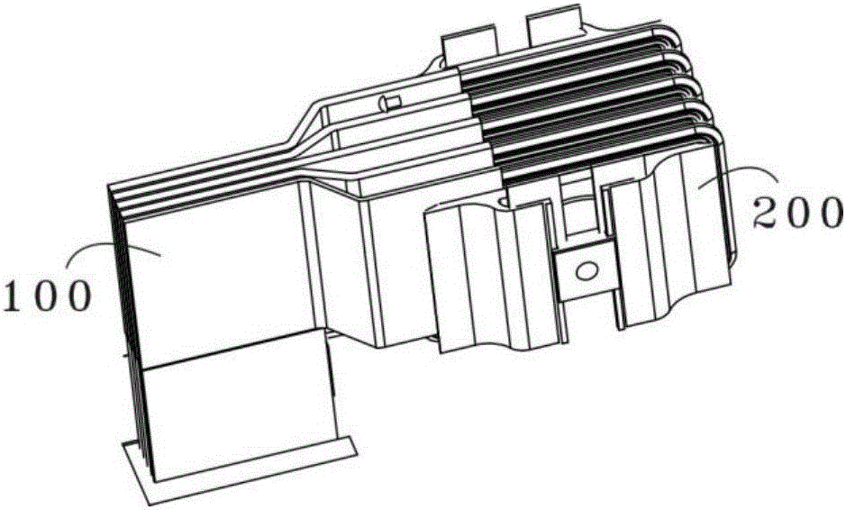
The invention discloses a plug structure. The plug structure comprises a plug unit and a communication unit, wherein the plug unit comprises a plurality of plug pieces; front ends of the plug pieces are spaced from one another to form intervals; rear ends of the plug pieces are gathered to form a gathered part; the communication unit comprises communication assemblies and fixing assemblies; the communication assemblies are spaced from one another to form communication space and are fixed by the fixing assemblies; and the intervals are inserted in the communication space to form electric connection. Firstly, by a plug mode of adding conductor units and connection units, heating to cause insulation damage and even short circuit due to poor contact can be completely eradicated; secondly, by conductors which are guided out from the bus duct, a plug box device for a guide-out requirement of a load of equipment can be added on an optional guided-out section of the bus duct; and thirdly, by conductor connecting plates, contact area can be greatly increased, and then, electric energy loss is reduced.

Description

technical field [0001] The invention relates to the technical field of power transmission and distribution equipment, in particular to a fast and safe plug-in type bus duct plug-in device. Background technique [0002] In recent years, with the rapid development of modern science and technology, and the emergence of modern engineering facilities and equipment, the electricity consumption of all walks of life has increased rapidly, especially the emergence of many high-rise buildings and large workshops. Cables can no longer meet the requirements in large current transmission systems, and the parallel use of multiple cables has brought a lot of inconvenience to on-site installation and construction connections; plug-in busbar connectors emerged as a new type of distribution wire Compared with it, it fully demonstrates its superiority in high current transmission. At the same time, due to the adoption of new technology and new technology, it greatly reduces the contact resista...

Claims


Application Information

Patent Timeline
Patent Type & Authority Applications(China)
IPC IPC(8): H02G5/00
CPCH02G5/007
Inventor 刘绍民
Owner 美嘉科技(镇江)有限公司
Learn More